The KYN61-40.5 type AC metal-clad withdrawable enclosed switchgear is widely used in 3-phase AC power systems with a frequency of 50Hz/60Hz and a rated voltage of 35kV. It is used for receiving and distributing electrical energy, as well as controlling, protecting, and monitoring circuits.
■ Operating Conditions
◎ Normal Operating Conditions
Ambient Temperature:
Maximum ambient temperature: +40℃
Minimum ambient temperature: -15℃
Relative Humidity:
Daily average relative humidity: ≤ 95%
Monthly average relative humidity: ≤ 90%
Maximum altitude of the switchgear installation site: 1000 meters
Seismic intensity: ≤ Grade 8
Installation site: Free from fire, explosion hazards, severe pollution, chemical corrosive gases, and violent vibration.
◎ Special Operating Conditions
According to the provisions of GB11022 and GB3906 standards, our company and the user can negotiate and reach an agreement on requirements beyond normal operation.
■ Main Technical Parameters
Item | Unit | Main Technical Parameters |
Rated Voltage | kV | 40.5 |
Rated Frequency | Hz | 50, 60 |
Rated Current | A | 630, 1250, 1600, 2000, 2500, 3150 |
Rated Short-Circuit Breaking Current | kA | 16, 20, 25, 31.5 |
Rated Making Current (Peak) | kA | 40, 50, 63, 80 |
3s Rated Thermal Stability Current | kA | 16, 20, 25, 31.5 |
Rated Dynamic Stability Current (Peak) | kA | 40, 50, 63, 80 |
1min Rated Power Frequency Withstand Voltage | kV | 95 |
Rated Lightning Impulse Withstand Voltage (Peak) | kV | 185 |
1min Rated Power Frequency Withstand Voltage Between Isolation Fractures | kV | 118 |
Rated Lightning Impulse Withstand Voltage (Peak) Between Isolation Fractures | kV | 215 |
Enclosure Protection Class | - | IP3X, IP4X |
Rated Operating Sequence | - | O-0.3s-CO-180s(15d)-CO |
Operating Mechanism and Operating Voltage | - | Spring energy storage type; Operating voltage: 110V, 220V |
■ Switchgear Structure
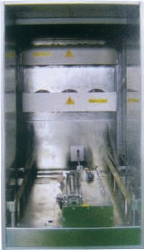
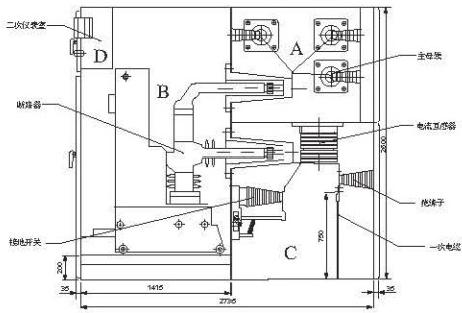
The KYN61-40.5 type switchgear consists of two main parts: a fixed cabinet body and withdrawable components (handcarts). According to the functions of electrical equipment inside the cabinet, it is divided into four functional units: Busbar Compartment (A), Handcart Compartment (B), Cable Compartment (C), and Instrument Compartment (D), as shown in the diagrams.
The cabinet shell and the partitions between each functional unit are made of aluminum-zinc coated steel plates or high-quality steel plates, which are bent and connected by bolts. The panel surface is processed by a spray coating process.
The withdrawable components of the switchgear can be configured with circuit breaker handcarts (vacuum or SF6 type), voltage transformer handcarts, metering handcarts, and isolation handcarts.
The enclosure protection class of the switchgear can reach IP4X, and the protection class is IP2X when the handcart compartment door is open. See Figure 1 for the structure.
■ Overall Dimensions and Weight of the Switchgear
Height (H) | mm | 2600 |
Width (W) | mm | 1200 (1400) |
Depth (D) | mm | 2800 |
Weight | kg | 850-3000 |
■ Enclosure, Partitions and Pressure Relief Devices
The enclosure of the KYN61-40.5 type metal-clad withdrawable switchgear adopts an internationally popular modular assembly structure. The enclosure and partitions are made of imported aluminum-zinc coated steel plates or high-quality cold-rolled steel plates, which are processed and bent by an imported flexible manufacturing system (FMS) and then assembled with bolts.
After electrostatic spraying treatment, the switchgear enclosure has an attractive appearance, with excellent surface adhesion, impact resistance, and corrosion resistance. The assembled switchgear ensures uniform dimensions and high mechanical strength.
The handcart compartment, busbar compartment, and cable compartment of the switchgear are each equipped with independent pressure relief channels, and pressure relief devices are installed above each compartment. In the event of an internal arcing fault, these devices can effectively release the high-pressure gas inside the cabinet, ensuring the safety of operators and the switchgear.
■ Handcart Compartment
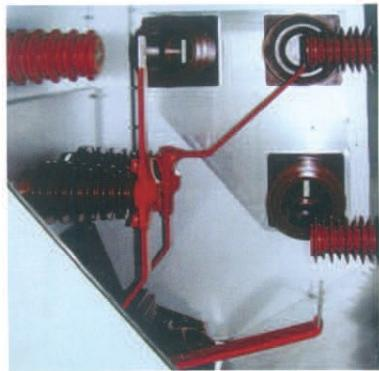
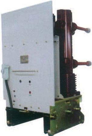
The handcart compartment is equipped with a handcart propulsion mechanism, which includes a lead screw propulsion mechanism, a handcart positioning mechanism, a main circuit shutter mechanism, and a secondary connection mechanism. See Figure 2 for the handcart compartment.
Lead Screw Propulsion Mechanism: When the handcart is moved into the cabinet from outside, the lead screw propulsion mechanism moves the handcart from the test position to the working position. The propulsion mechanism is equipped with a series of interlocking functions.
Handcart Positioning Mechanism: When the handcart reaches the test position, it is positioned and guided with the cabinet via the handcart positioning wheels and the mechanism (not via the moving wheels at the bottom of the handcart), ensuring correct connection between the handcart and the cabinet.
Main Circuit Shutter Mechanism: When the handcart moves from the test position to the working position, the shutter opens automatically; conversely, the shutter closes automatically. This prevents operators from touching live parts.
All types of handcarts have the same height and depth, and handcarts of the same specification are interchangeable.
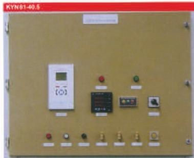
The panel of the circuit breaker handcart is equipped with manual closing/opening buttons, closing/opening mechanism indicators, a closing/opening counter, and an energy storage indicator, allowing for convenient and accurate monitoring of the handcart’s operating status. See Figure 3 for the handcart structural components.
■ Busbar Compartment
The main busbar runs through adjacent cabinets and is supported by insulators, bushings, and branch busbars. Depending on the rated current, the main busbar can be a single bar or double bars. The busbars are made of high-quality copper bars; the main busbar and branch busbars can be covered with insulating materials according to user requirements. Adjacent switchgears are isolated from each other by partitions and bushings. See Figure 4 for the busbar compartment.
■ Cable Compartment
The cable compartment can be installed with current transformers, earthing switches, arresters, etc., and can be connected to multiple parallel cables. The cable compartment has a large space, which greatly facilitates cable installation. For single-core cable outgoing, the cabinet bottom plate uses a slotted non-magnetic partition.
■ Instrument Compartment
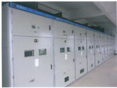
The low-voltage instrument compartment and its inner/outer panels can be installed with various secondary equipment according to different requirements. On the left side of the instrument compartment, there are inlet and outlet troughs for secondary control cables, which can adapt to various schemes for secondary cables and wires entering and exiting the cabinet. The instrument compartment is equipped with secondary small busbars for inter-cabinet connection. See Figure 5 for the instrument compartment panel.
■ Anti-Misoperation Mechanism
In accordance with domestic and international anti-misoperation requirements for switchgears, the KYN61-40.5 type metal-clad withdrawable switchgear is designed with a set of anti-misoperation interlocking devices. These devices fundamentally prevent dangerous situations and misoperations that may cause serious consequences, ensuring the safety of operators and the switchgear.
The specific main interlocking functions are as follows:
◎ The handcart can only be moved from the test/isolation position to the working position when the circuit breaker and earthing switch are in the open position.
◎ The circuit breaker can only be closed when the circuit breaker handcart is in the test or working position; moreover, the handcart cannot be moved after the circuit breaker is closed.
◎ The earthing switch can only be closed when the circuit breaker handcart is in the test/disconnected position.
◎ When the handcart is in the working position, the secondary plug of the control circuit cannot be disconnected (mechanism interlocked).
◎ The instrument compartment door is equipped with a prompt selector switch and an opening button to prevent accidental closing or opening of the circuit breaker.
◎ When the earthing switch is in the open position, the rear door cannot be opened, preventing personnel from accidentally entering the live compartment.
■ Main Electrical Components of the Primary Circuit
The vacuum circuit breaker is the most important electrical component in the primary circuit of the KYN61-40.5 type switchgear. It is the latest generation of circuit breakers representing the international advanced level, and complies with both GB and IEC standards.
Main Technical Parameters of HVF Vacuum Circuit Breaker
Circuit Breaker Model | HVF7252 | HVF7253 | HVF7254 | HVF7256 | HVF7257 |
Rated Voltage (kV) | 40.5 |
Rated Current (A) | 1250 | 1600 | 2000 | 2500 | 3150 |
Rated Breaking Current (kV) | 31.5 |
Dynamic Stability Current (kA) | 80 |
3s Thermal Stability Current (kA) | 31.5 |
1min Power Frequency Withstand Voltage (kV) | 95 |
Impulse Withstand Voltage (kV) BIL | 185 |
Operating Voltage (V) | DC 48, 110, 220; AC 110, 220 |
Operating Sequence | O-0.3s-CO-3min-CO |
Closing Time | ≤60ms |
Opening Time | ≤45ms |
Reclosing Time | ≤145ms |
Main Technical Parameters of the HVF Vacuum Circuit Breaker Operating Mechanism
Closing/Opening Coil Voltage V (DC) | 110 | 220 | 125 | 250 |
Closing/Opening Coil Power Consumption (W) | 400 | 400 | 400 | 400 |
Energy Storage Motor Operating Voltage V (DC) | 110 | 220 | 125 | 250 |
Energy Storage Motor Power Consumption (W) | 500 | 500 | 400 | 500 |
■ Main Electrical Components of the Secondary Circuit
◎ Protection Relays
The protection relays of the KYN61-40.5 type switchgear mainly adopt microcomputer-based integrated protection relays. They can also be configured with microcomputer-based measurement, control and protection devices produced by other companies according to user requirements.

Symbol | Name | Symbol | Name |
K1 | Anti-Pickup Relay | M1 | Motor Operating Mechanism |
S3, S21, S22, S5 | Energy Storage Limit Switch | Y1 | Opening Coil |
Y9 | Closing Coil | R | Resistor |
S1 | Auxiliary Switch | XO | Plug |
Switch Status:
Uncharged, open position, handcart in test position.
This diagram is for the standard KYN61/40.5KV circuit breaker.
■ Arrangement and Installation
◎ Switchgear Foundation Embedding
The construction of the switchgear foundation shall comply with the relevant provisions in the Technical Code for Construction and Acceptance of Electric Power Construction.
The switchgear must be installed on the foundation frame pre-embedded in the power distribution room floor, which is manufactured in accordance with the typical drawings provided by our company.
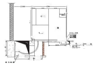
The frame is welded to the pre-embedded channel steel in the concrete foundation (angle steel or flat steel can also be used). The surface of the channel steel shall be 5mm higher than the concrete foundation, and the pre-embedding of this foundation channel steel shall be completed by the civil engineering team. The manufacture and installation of the switchgear installation frame shall be completed by electrical construction personnel. Before welding the frame to the foundation channel steel, the frame must be level. The adjustment method is to add adjustable metal gaskets between the frame and the foundation channel steel. After the frame is leveled, it shall be welded to the foundation channel steel. Finally, the second-phase concrete foundation construction shall be carried out, i.e., smoothing the foundation surface with cement mortar. The frame shall be made of 10# channel steel and shall be at least 50mm higher than the ground. See Figure 6 for the installation of the frame and foundation channel steel.
Allowable flatness tolerance: ±1mm/m
Allowable straightness tolerance: ±1mm/m; however, the total deviation within the total length of the frame shall not exceed 2mm
The frame shall have reliable grounding, and the grounding shall use a 40×40mm galvanized steel strip. When a group of switchgears is arranged in a long line, the foundation frame shall be grounded at both ends.
After the completion of the supplementary layer of the power distribution room floor, attention shall be paid to backfilling the lower part of the foundation frame without leaving any gaps.
The foundation frame shall not be subjected to any harmful impact or pressure, especially during the installation process.
If the above conditions are not fully met, it may affect the installation of the switchgear, the movement of the handcart, and the opening of the handcart compartment door and cable compartment door.
◎ Switchgear Installation
The KYN61-40.5 metal-clad withdrawable switchgear shall be installed in a dry, clean, and well-ventilated power distribution room. During installation, it is required that the foundation frame of the switchgear in the power distribution room and the indoor floor have passed completion acceptance, and the door and window decoration as well as the indoor lighting and ventilation projects in the power distribution room shall be basically completed.
For the specific installation method of the switchgear, please refer to the Installation and Operation Manual separately.
■ Items Provided with the Complete Product
◎ Product Certificate of Conformity
◎ Factory Test Report
◎ Packing List
◎ Operation Manual
◎ Equipment List
◎ Secondary Wiring Diagram
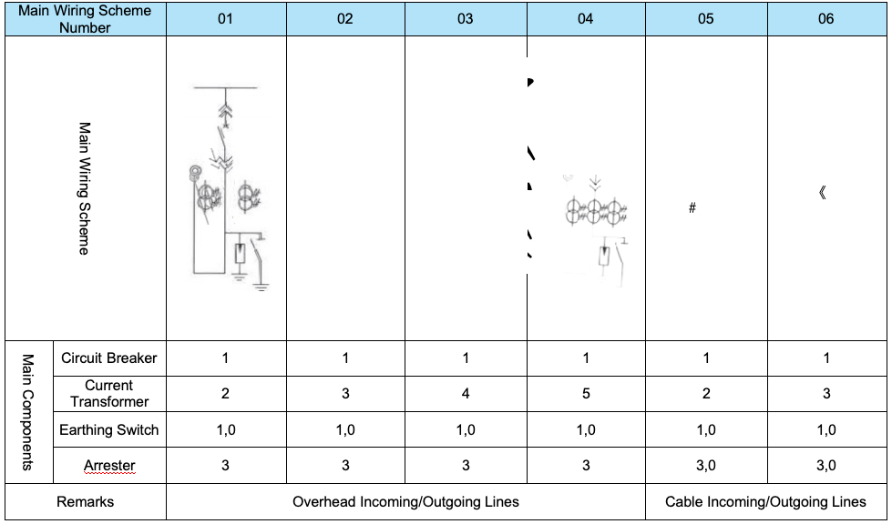
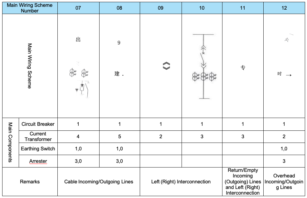
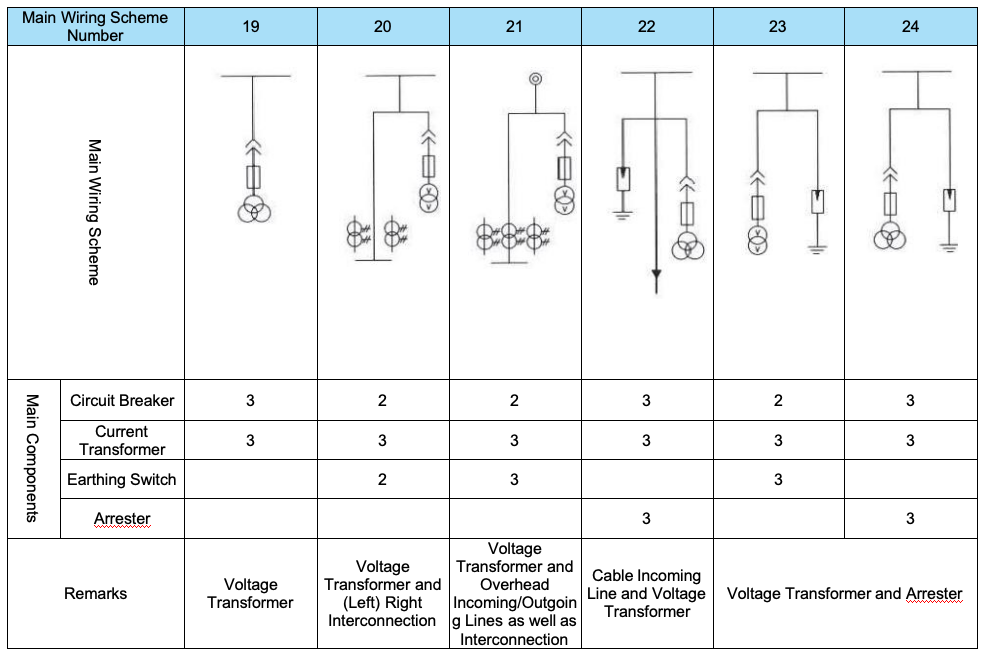
■ Main Circuit Scheme
 English
  French
  Icelandic
  Georgian
  Slovak
  Slovenian
  Latvian
  Bosnian
  Ukrainian
  Serbian
  Croatian
  Belarusian
  Romanian
  Estonian
  Hungarian
  Czech
Czech  Catalan
  Norwegian
  Lithuanian
  Albanian
  Hindi
Hindi  Italian
  Finnish
  Arabic
  Danish
  Bulgarian
  Thai
Thai  Polish
  Swedish
  Greek
Greek  Portuguese
  Dutch
Dutch  Turkish
  Russian
  Deutsch
  Korean
  Japanese


")