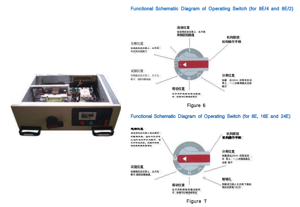
Drawer units are equipped with reliable mechanical interlocking devices, controlled by an operating handle, and have clear and accurate positions including opening, closing, test, withdrawn, and isolation. The functions of the operating mechanism are shown in the table below.
To enhance safety, padlocks can be added after the operating handle is positioned, with a maximum of three padlocks allowed.
After the drawer unit is in place, operations must be strictly performed in accordance with the functions and positions of the operating switches listed in Figure 6 and Figure 7. Please note that improper operation may damage easily damaged components, so users should pay attention during use.
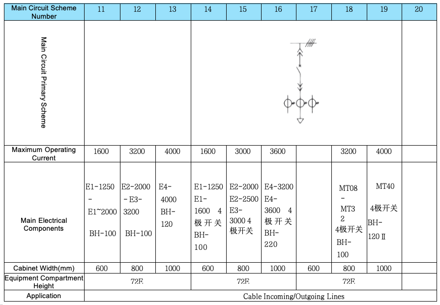
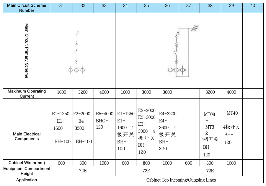
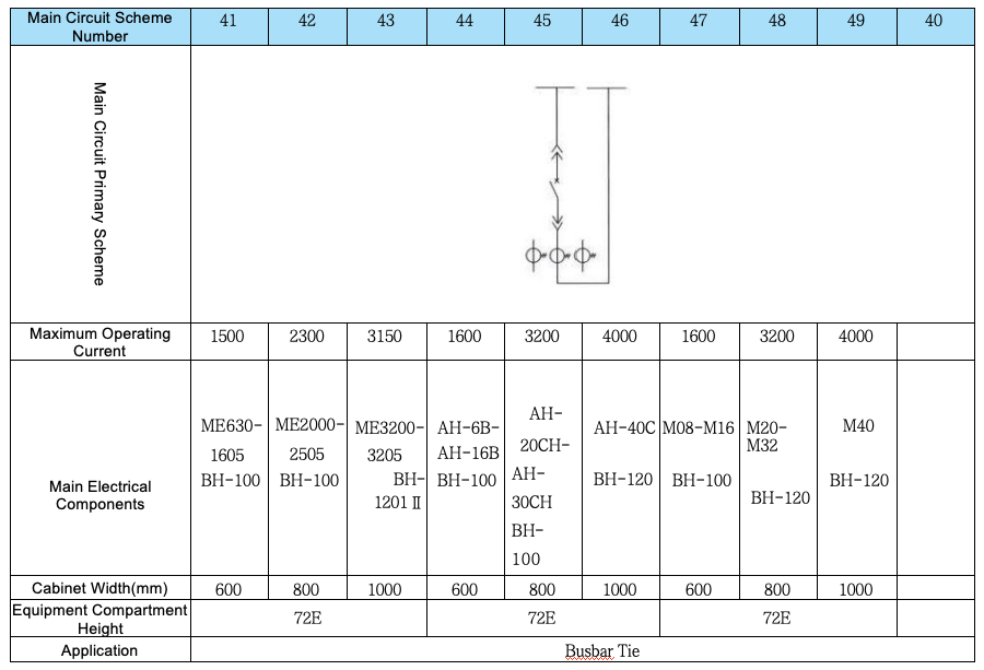
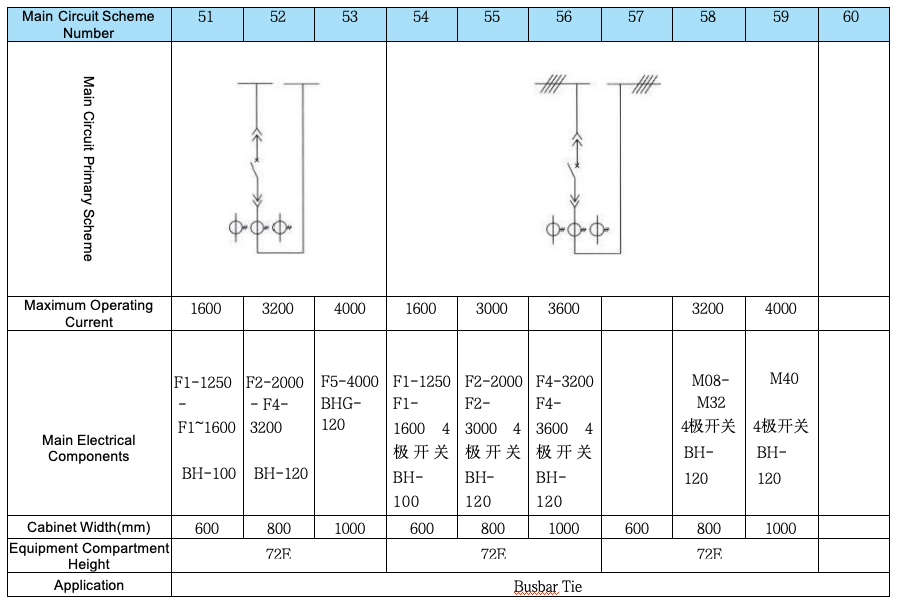
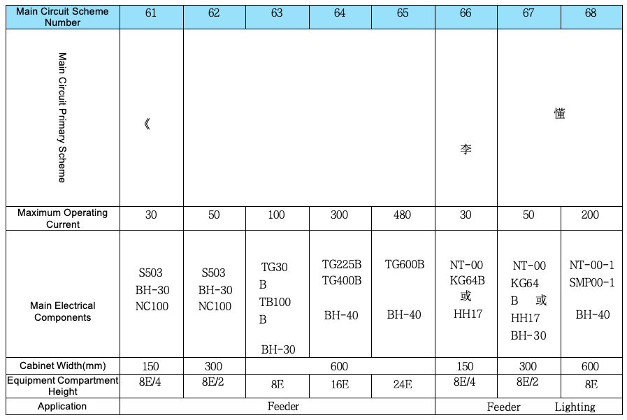
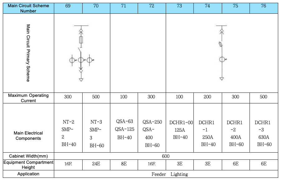
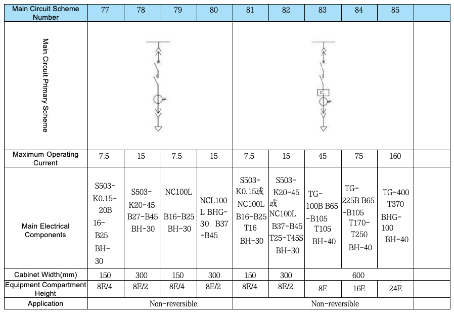
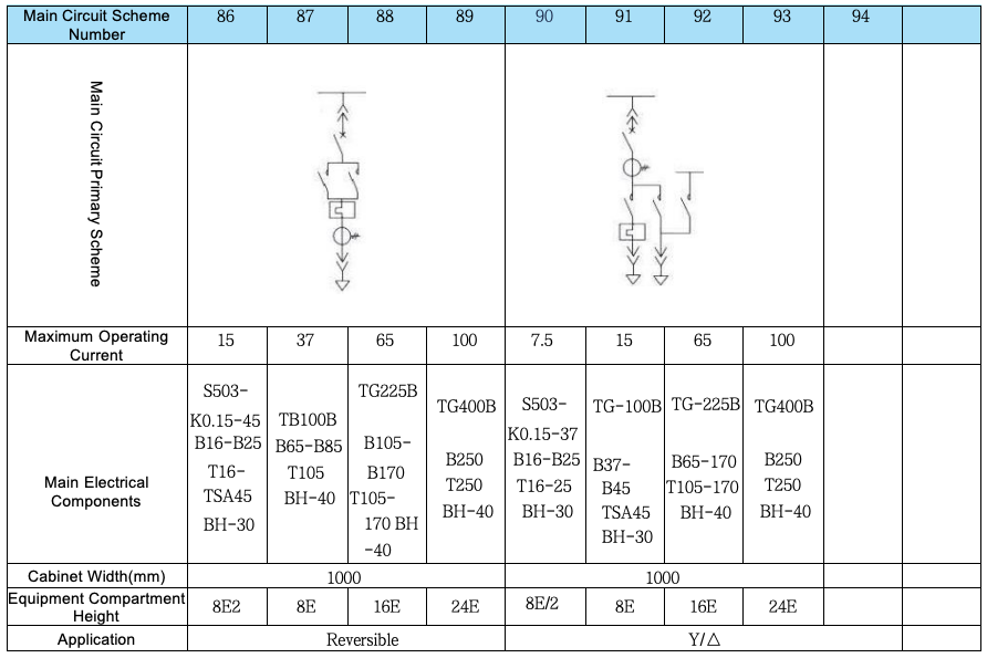
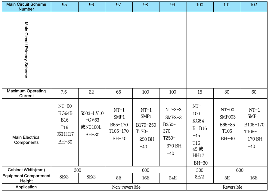
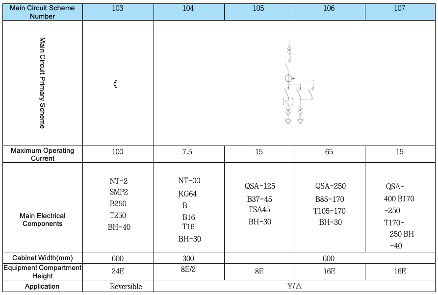
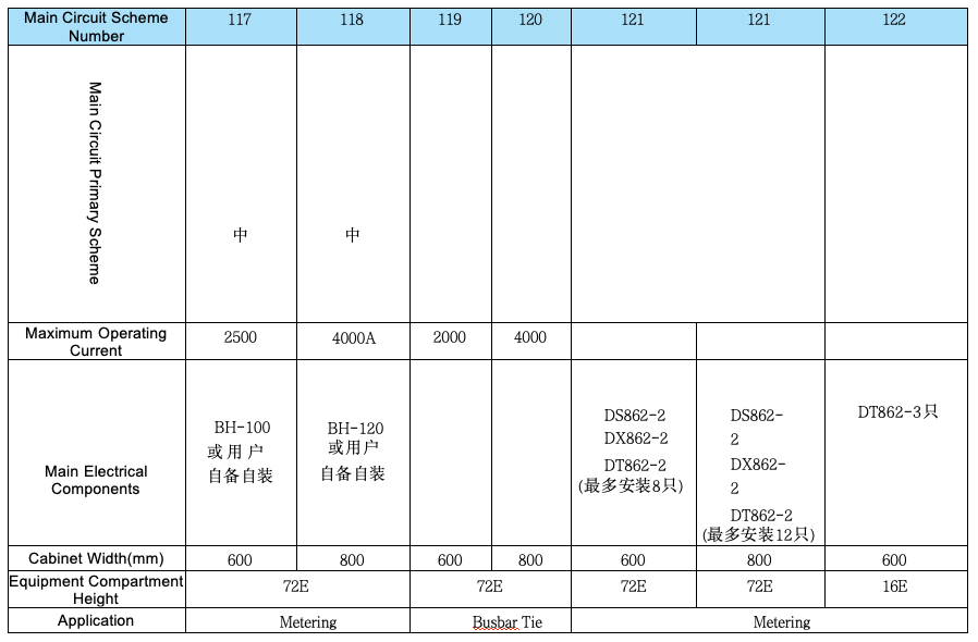
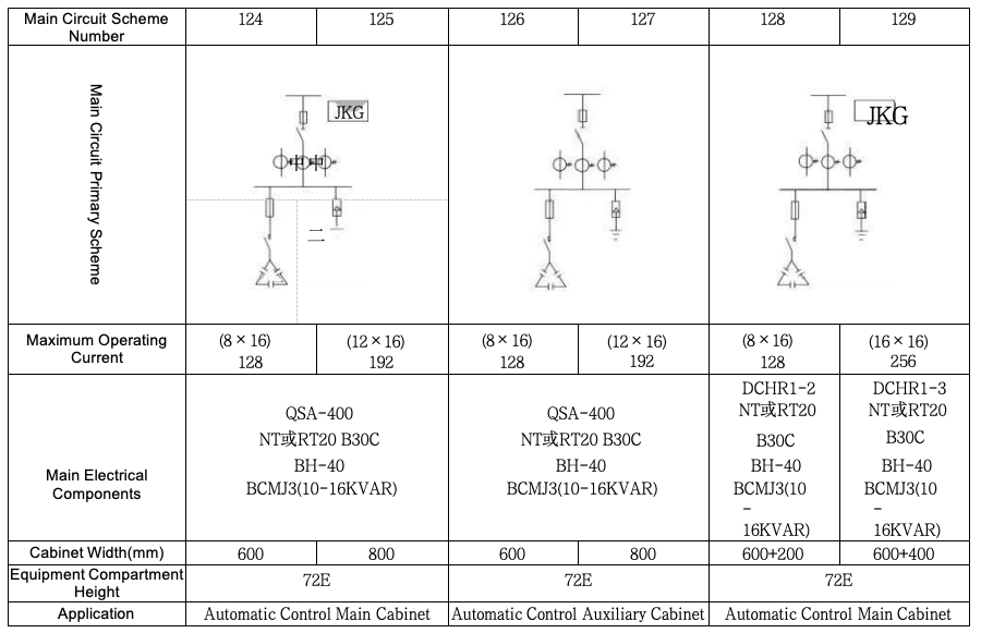
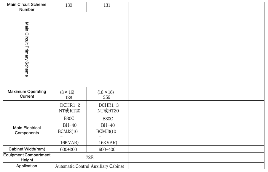
■ Arrangement and Combination of Primary Schemes
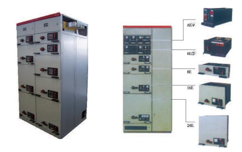
The total height of the Functional Unit Compartment is 72E.
In the same device, the general arrangement rule of functional units is: small functional units are placed on the upper part, and large functional units are placed on the lower part.
Four 8E/4 drawers form one 8E Installation Unit;
Two 8E/2 drawers form one 8E Installation Unit;
Or two 8E/4 drawers and one 8E/2 drawer form one 8E Installation Unit.
The number of current transformers shown in the scheme is the maximum number of installations for that scheme (In Schemes 01-19 and 21-39, one additional current transformer can be added for the reactive power compensation circuit). In actual use, the number of current transformers can be reduced or omitted as needed.
The device has two depth specifications:
600mm (for MCC single-side operation cabinets);
1000mm (for PC cabinets and MCC double-side operation cabinets).
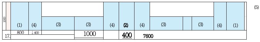
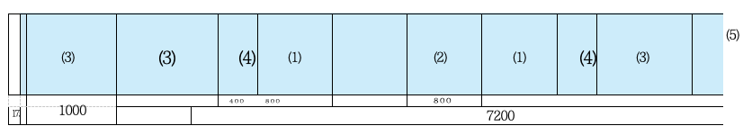
It is recommended that PC and MCC be arranged separately. When a segmented functional panel is used, mixed assembly of PC and MCC in the same cabinet is allowed.
When the two types of devices (PC and MCC) are arranged adjacent to each other:① Deepen the single-side operation MCC to 1000mm, as shown in Diagram Example 2 below.② When the MCC double-side cabinet (or the MCC single-side cabinet with a depth of 600mm) is arranged adjacent to the PC cabinet, a transfer cabinet (with a width of 400mm) must be added between the two cabinets, as shown in the diagram example below.
■ Combination Modes of Switchgears
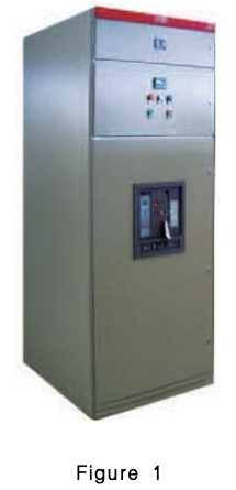
1.Power Receiving Cabinet (PC Cabinet)
2.Tie Cabinet (PC Cabinet)
3.Motor Control Cabinet (MCC Cabinet)
4.Main Busbar Transfer Cabinet
5.Side Panel
■ Installation, Assembly and Maintenance
The overall dimensions of the device are shown in Table 1 and Table 2.
After the device is delivered to the destination, first check whether the packaging is intact. If it is not to be installed immediately, it should be stored in a dry and clean place.
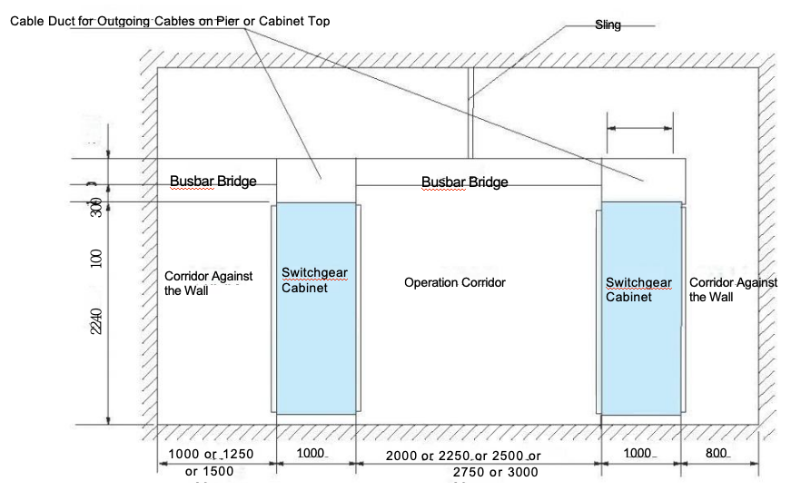
The device is recommended for free-standing installation (not against the wall) and can also be installed in a wall-mounted manner. The installation foundation surface must be level; the horizontal error of the foundation channel steel is 1/1000, and the total length deviation is 3mm.
For the screw fastening of all conductive parts, Grade 8.8 bolts and lock washers are recommended. The calculated tightening torque values are shown in the table below.
The accessories for the MCC scheme include two specifications of cable head sheaths and a certain number of copper connectors for the secondary circuit. After the cables are connected, the bottom of the device should be sealed to prevent small animals from crawling into the cabinet and causing short-circuit accidents.
After the device is installed or adjusted, the following inspections and tests must be conducted before it is put into operation:① Check whether the electrical equipment installed in the device and the control wiring comply with the factory drawing requirements.② Manually operate various switches; the operation should be flexible without abnormalities or jamming.③ Check whether the mechanical interlocking mechanism and electrical interlocking device act correctly and reliably, which should meet the system requirements.④ Check whether the insulation resistance of the main circuit and control circuit meets the specified requirements.⑤ Check whether the electrical equipment installed in the device is in good condition and complies with the technical specifications of the equipment itself.⑥ Check whether there are foreign objects inside the device and whether the mounting screws of each component are loose.
Operating Instructions for Withdrawable MCC
① The bottom of the drawer must be correctly inserted into the guides before being pushed into the cabinet; otherwise, problems such as drawer damage or inability to pull it out may occur.② The symbol marks and functions on the panel of 8E/4 and 8E/2 drawers are shown in Figure 6. The arrow from the open position "O" to the operating position "1" in the figure indicates the following operation: first push the operating handle inward, then rotate the handle from "O" to "1". When returning, no pushing is required—just rotate the handle from "1" to "O", and the handle will pop out automatically after being released.③ The symbol marks and functions on the panel of 8E-24E drawers are shown in Figure 7. When the handle reaches the operating position "", the mechanism releases the mechanical interlock of the main switch. At this time, the main switch can be closed or opened; however, after the main switch is opened or closed, the handle of the interlocking mechanism cannot be operated.
There is a small plastic box on the door at the lower right corner of the symbol mark, which is the door interlocking mechanism. The operation process is as follows: When the drawer is in the operating position, if you need to open the door, first pull out the small box, then insert a screwdriver into the hole and move the lock catch downward to open the door. After opening the door, be sure to close the plastic box; otherwise, the original protection class will be damaged.
Table 4
Bolt Specification | Tightening Torque (Nm) |
M6 | 9.5 |
M8 | 25 |
M10 | 45 |
M12 | 80 |
M16 | 200 |
 English
  French
  Icelandic
  Georgian
  Slovak
  Slovenian
  Latvian
  Bosnian
  Ukrainian
  Serbian
  Croatian
  Belarusian
  Romanian
  Estonian
  Hungarian
  Czech
Czech  Catalan
  Norwegian
  Lithuanian
  Albanian
  Hindi
Hindi  Italian
  Finnish
  Arabic
  Danish
  Bulgarian
  Thai
Thai  Polish
  Swedish
  Greek
Greek  Portuguese
  Dutch
Dutch  Turkish
  Russian
  Deutsch
  Korean
  Japanese


")