 English
  French
  Icelandic
  Georgian
  Slovak
  Slovenian
  Latvian
  Bosnian
  Ukrainian
  Serbian
  Croatian
  Belarusian
  Romanian
  Estonian
  Hungarian
  Czech
Czech  Catalan
  Norwegian
  Lithuanian
  Albanian
  Hindi
Hindi  Italian
  Finnish
  Arabic
  Danish
  Bulgarian
  Thai
Thai  Polish
  Swedish
  Greek
Greek  Portuguese
  Dutch
Dutch  Turkish
  Russian
  Deutsch
  Korean
  Japanese
 PRODUCT CENTER
CONTACT US
If you are interested in cooperation, please contact us immediately, we will give you feedback as soon as possible!

- ]">
-
GCK Low-Voltage Switchgear Cabinet
Category :
hiddenValue
PRODUCT DETAILS
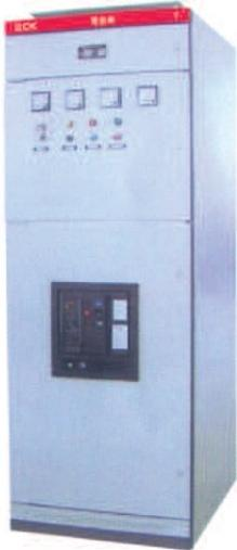
■ Product Overview
The GCK low-voltage switchgear cabinet is a product designed in the early 1990s by the Tianjin Electric Rotation Research Institute. Our company has signed a technology transfer agreement with the Tianjin Electric Rotation Research Institute. This cabinet incorporates the advantages of domestic low-voltage cabinets and represents a new generation of products, with the following characteristics:
The product adopts a modular structure. Its cabinet frame consists of columns and rails formed by stamping thin steel plates using a special process. Special-purpose connectors, doors, and various mounting plates are all fastened together with screws.
This cabinet frame structure eliminates welding deformation and stress.
The external dimensions of the frame, as well as the external dimensions and hole-opening dimensions of spare parts, are designed with modular variations, facilitating selection by engineering designers.
The cabinet is available in three types: drawer-type, fixed-type, and hybrid-type.
Spare parts feature high universality and strong adaptability. The withdrawal process is convenient and flexible, with no jamming or collision. The centerlines of moving contacts and fixed contacts are aligned. Due to its special design, the grounding contacts are 5mm longer than the phase contacts, and the contacts maintain tight contact. When the unit is put into operation, the grounding contacts make contact before the main contacts; when withdrawn, the grounding contacts disconnect after the main contacts. This ensures the personal safety of operators. The cabinet also offers advantages such as operating position, test position, and withdrawn position.
The front-left side of the cabinet frame is the control unit compartment, separated by steel partition plates into several small compartments. This design isolates different circuits to prevent the expansion of line faults. The protection class reaches IP40-50, and the maximum current capacity can reach 6300A.
This series of products features high breaking capacity, excellent dynamic and thermal stability, advanced and reasonable structure, practical electrical schemes, strong seriality and universality, and flexible combination of various scheme units. A single cabinet can accommodate multiple circuits, saving floor space. It also has an attractive appearance, high protection class, safety and reliability, and easy maintenance.
The GCK series withdrawable switchgear cabinets comply with GB7251.1 Low-Voltage Switchgear and Controlgear - Part 1: Type-Tested and Partially Type-Tested Assemblies.
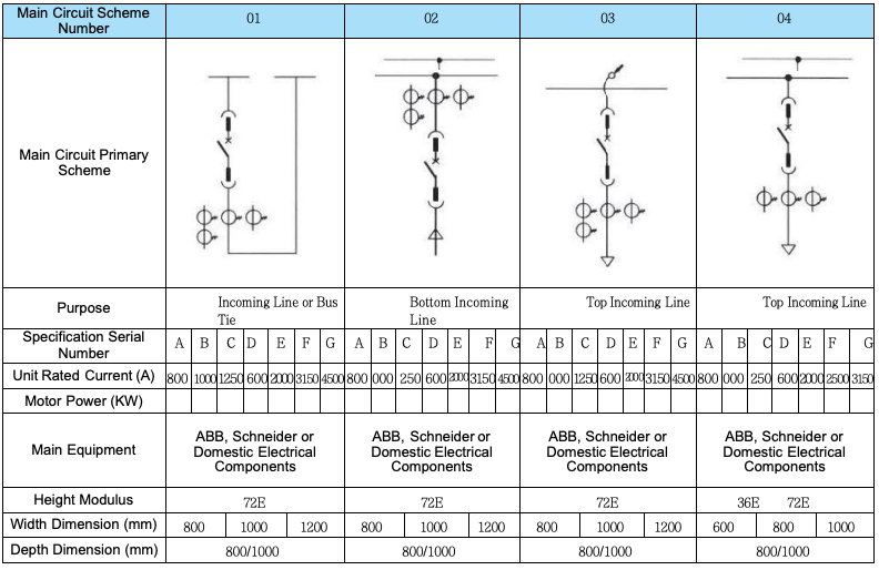
■ Design Features
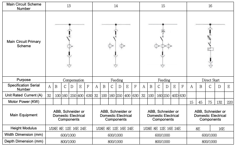
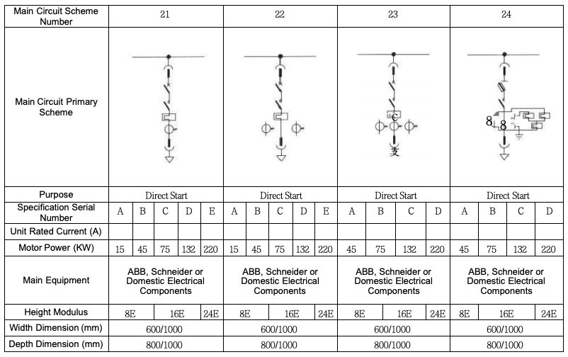
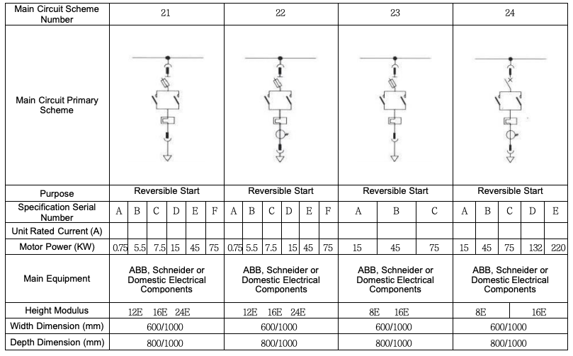
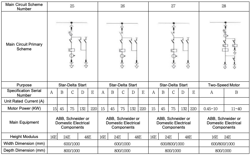
For outgoing line circuits or incoming line circuits with a current exceeding 630A, the switch body should preferably be of withdrawable type or fixed type;
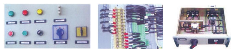
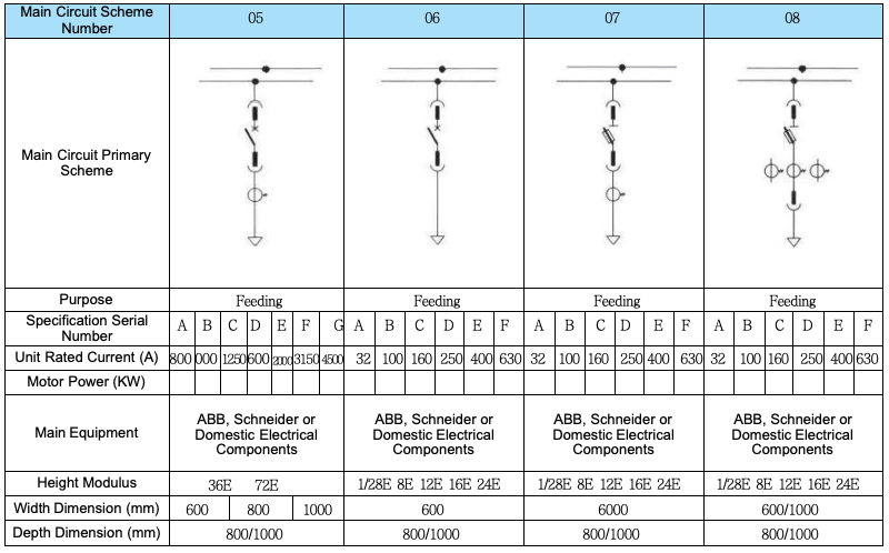
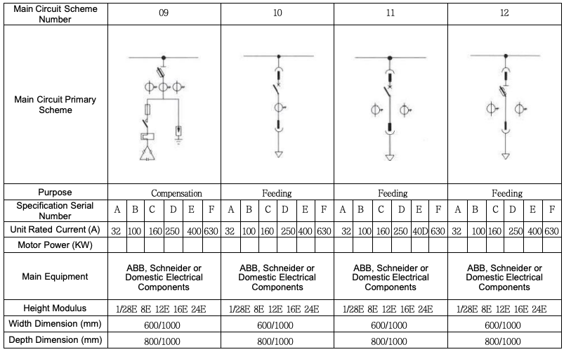
Power feeding circuits can be of withdrawable (drawer-type) or plug-in type, featuring reliable performance, simple structure, and convenient and quick maintenance and replacement;
For motor control circuits, the withdrawable (drawer-type) is mostly used, while fixed installation is more economical and has high reliability.
■ Design Specifications
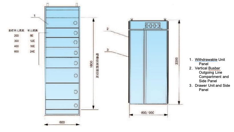
According to design requirements, 1/2-size drawers can be selected within a 4-modular unit;
In fixed design, components can be installed within a single modular unit;
This cabinet generally adopts rear outgoing lines. If side outgoing lines are required, this can also be implemented (side outgoing lines can be paralleled with rear outgoing lines in cabinet arrangement).
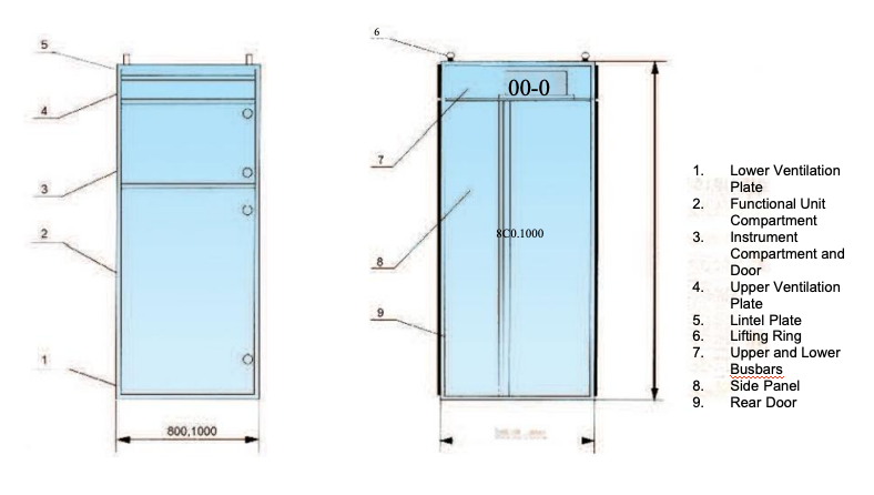
■ Structural Features
The basic cabinet frame of this product series adopts a modular assembled structure. All structural components of the cabinet frame are connected to each other by screw fastening to form a basic frame. Then, parts such as doors, baffles, partitions, drawers, mounting brackets, as well as busbars and electrical components are added as needed to assemble a complete switchgear cabinet. This cabinet has the following features:
The frame is made of special-shaped steel, positioned by connecting plates, and adopts a bolted structure without welding, which eliminates welding deformation and stress and improves installation accuracy.
The mounting holes of the frame and components vary according to the modulus E=25mm.
Internal structural components undergo galvanized treatment. The exterior, after acid pickling and phosphating treatment, is coated with electrostatic epoxy powder.
The drawer unit takes a height of 200mm (i.e., 8E) as the benchmark.
■ Operating Conditions
The altitude of the operating environment shall not exceed 2000m;
The ambient air temperature shall not be higher than +40℃, and the average temperature within 24 hours shall not be higher than +35℃; the minimum ambient air temperature shall not be lower than -5℃;
Atmospheric conditions: Clean air; the relative humidity shall not exceed 50% when the maximum temperature is +40℃, and higher relative humidity is allowed at lower temperatures (e.g., 90% at +20℃);
It shall be used in locations free from fire and explosion hazards, severe pollution, chemical corrosion, and severe vibration;
The inclination angle of the product relative to the vertical plane shall not exceed 5 degrees during installation.
This product is suitable for transportation and storage under the following temperatures: -25℃ to +55℃, and shall not exceed +70℃ for a short period (no more than 24 hours);
If the above operating conditions cannot be met, the user shall propose to the manufacturing company for negotiation and resolution when placing an order.
■Technical Parameters
Item | Specification |
Compliant Standards | GB7251.1 |
NAMEICS 2-322 | |
JEM 1195 | |
JB/T 9661 | |
Protection Class | IP40 |
Rated Insulation Voltage (V) | 660 |
Rated Voltage (V) | 380, 660 |
Frequency (Hz) | 50 |
Withstand Voltage (V/min) | 2500, 3000 |
Environment - Altitude | Not higher than 2000 meters |
Environment - Ambient Temperature | -5℃ ~ +40℃ (average temperature not exceeding 35℃ within 24 hours); Storage and Transportation Temperature: +25℃ ~ +53℃ |
Environment - Relative Humidity | Not exceeding 85% |
Brake Motor Capacity (at 380V) | 0.25 ~ 155 kW |
Drawer Mechanical Service Life | Not less than 100 times |
Horizontal Busbar (A) | 1600, 2500, 3150, 4000, 5000, 6300 |
Vertical Busbar (A) | 1250 |
Main Circuit Connectors | 100, 250, 400, 630 |
Auxiliary Circuit Connectors | 16 |
Maximum Rated Operating Current of Feeding Circuit | 630 A |
Rated Operating Current of Power Receiving Circuit | 1000, 1600, 2000, 2500, 3150 A |
Rated Short-Time Withstand Current (kA) | R-15, M-30, SLL5-50 |
Rated Peak Withstand Current (kA) | 30, 65, 110 |

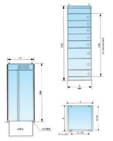

A | B |
600 | 800 |
600 | 1000 |
800 | 800 |
800 | 1000 |
1000 | 800 |
1000 | 1000 |


")