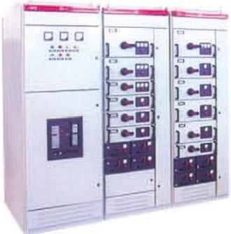
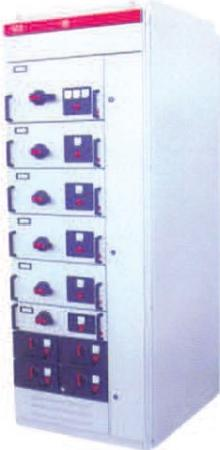
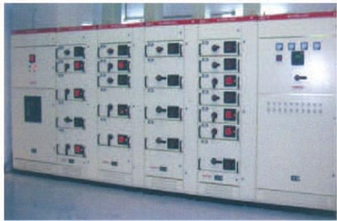
■ Product Overview
GCS low-voltage switchgear is the latest type of low-voltage distribution cabinet independently developed by the Ministry of Electric Power Industry and the Ministry of Machinery Industry. It has a maximum busbar capacity of 5000A, with stable, safe and reliable performance.
■ Product Features
The main frame of the device adopts an 8MF section steel frame, with two structural types: assembled and partially welded, featuring high mechanical strength. The two sides of the section steel are provided with φ9.2mm mounting holes with moduli of 20mm and 100mm respectively, enabling flexible and convenient internal installation.
The design of the device complies with the following series of standards:
IEC60439-1: Low-Voltage Switchgear and Controlgear Assemblies
GB7251.1-2005: Low-Voltage Switchgear and Controlgear Assemblies
JB/T9661: Low-Voltage Withdrawable Switchgear
The functional compartments of the device are strictly separated, and the functional roles of each unit are relatively independent, with a high protection class.
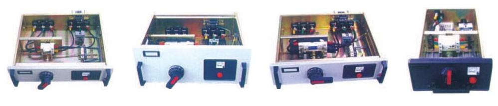
The drawers of functional units are small, compact and can be easily interchanged.
The drawer panel is clearly marked with positions such as "on", "off", "test" and "withdrawn", and the drawer is equipped with a mechanical interlocking device.
Feeder cabinets and motor control cabinets are equipped with dedicated cable compartments. The connection between functional units and cables in the cable compartment is realized through adapters or adapter copper bars, which not only improves the reliability of cable use but also greatly facilitates the user's cable installation and maintenance.
Features of the device:A. Improve the heat capacity of adapters, significantly reducing the additional temperature rise of connectors, cable heads and partition plates caused by the temperature rise of adapters.B. The separation between functional units and between compartments is clear and reliable, preventing the failure of one unit from affecting the operation of other units, thus confining faults to the smallest range.C. The horizontal arrangement of busbars ensures good dynamic and thermal stability of the device, which can withstand the impact of 80/176kA short-circuit current.D. The maximum number of circuits in a single MCC cabinet is 22, fully considering the needs of industries such as large-capacity power plants and factory and mine systems for automated electric door (motor) groups.E. The connection between the device and external cables is completed in the cable compartment. Cables can enter and exit from the top and bottom. The zero-sequence current transformer is placed in the cable compartment, facilitating installation and maintenance.F. For the same power distribution system, the short-circuit current can be limited through the matching of current-limiting reactors, stabilizing the busbar current at a certain value, and partially reducing the requirements for the short-circuit strength of components.G. Drawer units are equipped with a sufficient number of secondary connectors (32 pairs for 1 unit and above, 20 pairs for 1/2 unit), which can meet the requirements for the number of contact points in computer interfaces and automatic control circuits.
■ Operating Conditions
The ambient air temperature shall not be higher than +40℃ or lower than -5℃, and the average temperature within 24 hours shall not exceed +35℃.
For indoor installation and use, the altitude of the installation site shall not exceed 2000m.
The relative humidity of the ambient air shall not exceed 50% at the maximum temperature of +40℃, and a higher relative humidity is allowed at lower temperatures (e.g., 90% at +20℃). Attention shall be paid to the possible impact of condensation caused by temperature changes.
The inclination of the equipment installation from the vertical plane shall not exceed 5 degrees.
The equipment shall be installed in a place free from severe vibration and impact, and where electrical components will not be corroded.
For special requirements, negotiation with the manufacturer is possible.
■ Performance Indicators
The design of the device complies with the following series of standards: |
IEC 60439-1 | Low-Voltage Switchgear and Controlgear Assemblies |
GB 7251.1-2005 | Low-Voltage Switchgear and Controlgear Assemblies |
JB/T 9661 | Low-Voltage Withdrawable Switchgear |
■ Application Scope and Purpose
This device is used in power distribution systems for industries such as power plants, petroleum, chemical engineering, metallurgy, textiles, and high-rise buildings. In places with high automation (e.g., large power plants, petrochemical systems) that require computer interfaces, it serves as a low-voltage complete power distribution device for power distribution, centralized motor control, and reactive power compensation in power generation and supply systems with the following parameters: three-phase AC frequency of 50 (60) Hz, rated operating voltage of 380V (400V) (600V), and rated current of 5000A or below.
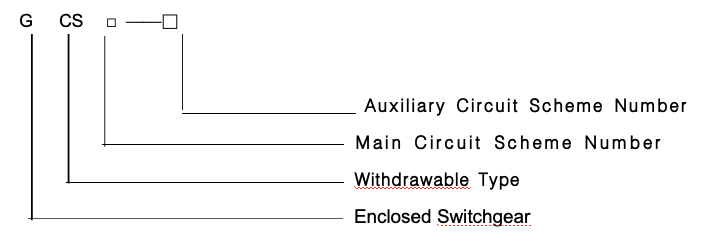
■ Product Model and Its Meaning
■ Technical Parameters
Parameter Category | Specific Item | Specification |
Rated Voltage of Main Circuit (V) | AC 380 (400) (660) |
Rated Voltage of Auxiliary Circuit (V) | AC 220, 380 (400); DC 110, 220 |
Rated Frequency (Hz) | 50 (60) |
Rated Insulation Voltage (V) | 660 (1000) |
Rated Current (A) | Horizontal Busbar | ≤ 5000 |
| Vertical Busbar (MCC) | 1600 |
Rated Short-Time Withstand Current of Busbar (Iₛ) | 50 (80) kA |
Rated Peak Withstand Current of Busbar | 105, 176 kA |
Power Frequency Test Voltage (V/1min) | Main Circuit | 2500 |
Busbar System | Auxiliary Circuit | 1760 |
| Three-Phase Four-Wire System | A, B, C, PEN |
| Three-Phase Five-Wire System | A, B, C, PE, N |
Protection Class | IP40 |
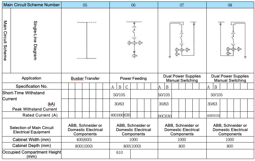
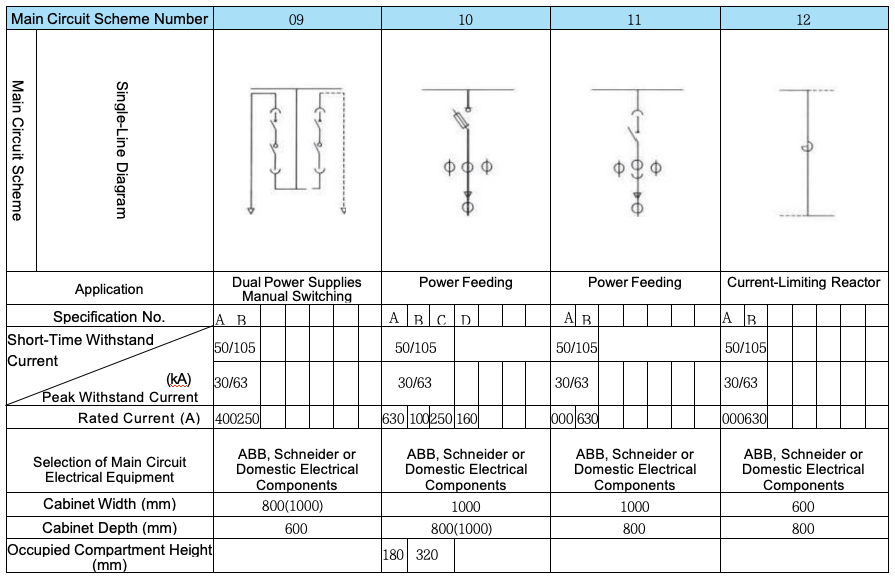
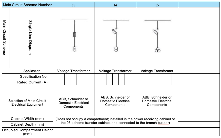
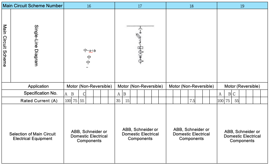
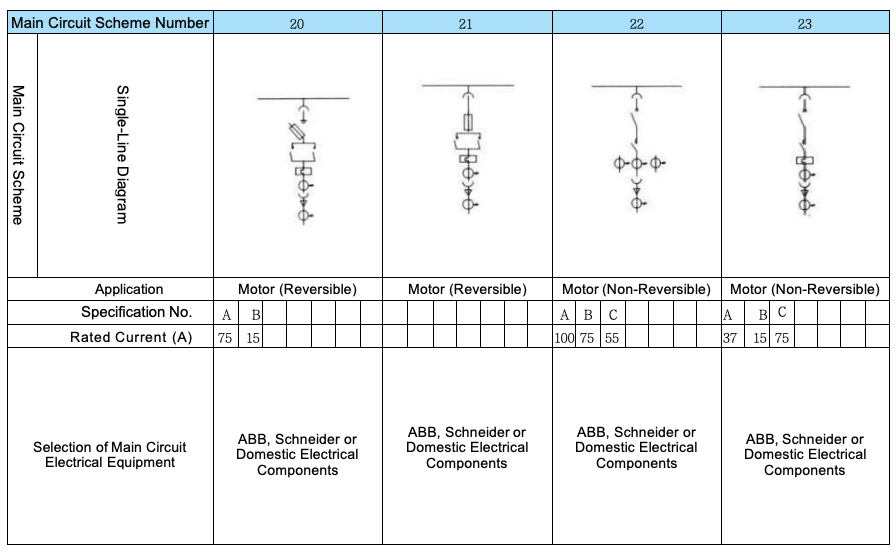
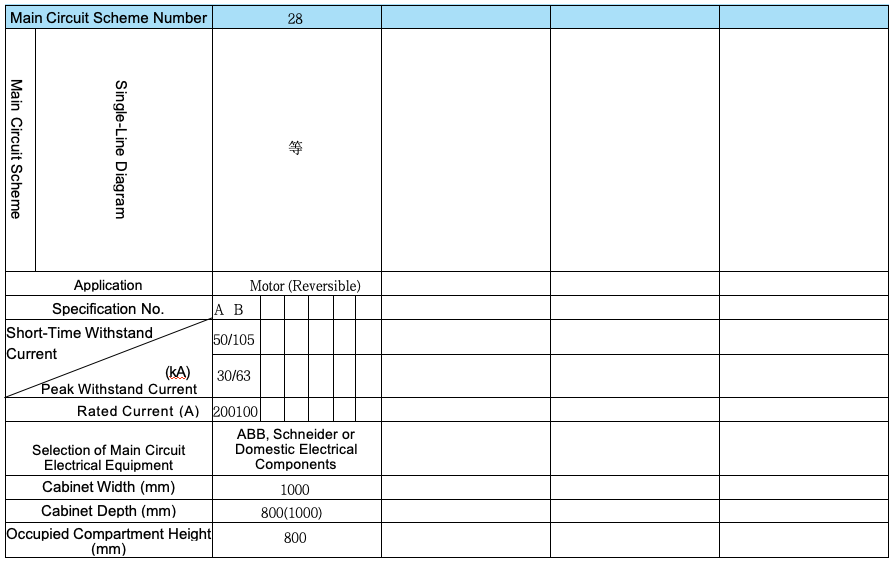
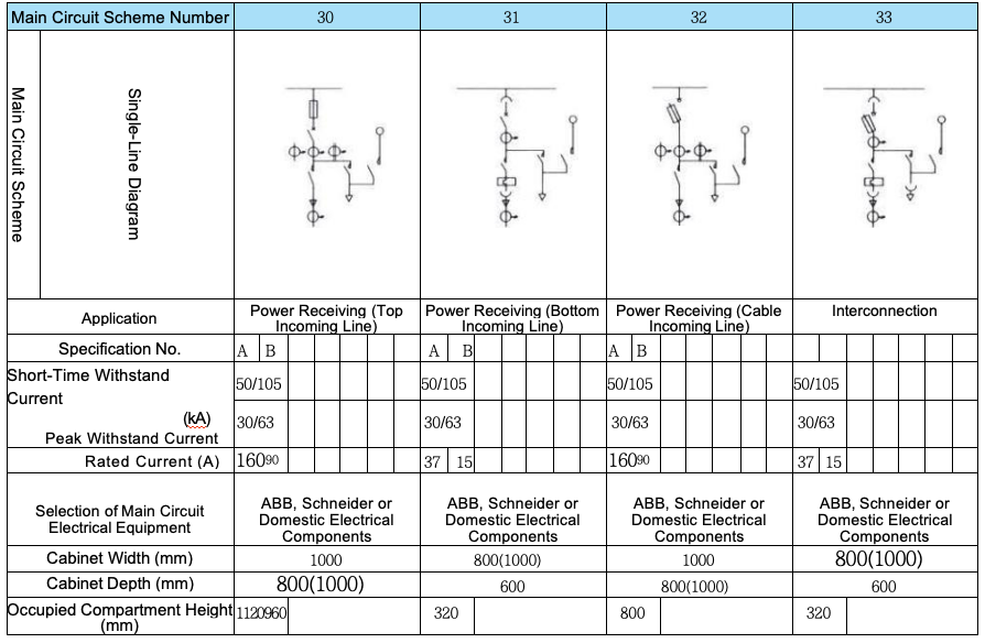
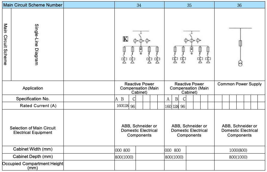
■ Main Circuit Schemes
The device offers 32 groups of main circuit schemes with 118 specifications, excluding derivative schemes and specifications caused by changes in the control and protection of auxiliary circuits. These main circuit schemes are compiled based on opinions collected from a wide range of design, renovation, testing, and user departments, covering the needs of power generation, power supply, and other power users. With a rated operating current of 5000A, they are suitable for distribution transformers with a rating of 3150 kVA and below. In addition, capacitor compensation cabinets are designed to meet the requirement of improving power factor in power supply systems, and reactor cabinets are designed to cater to the need for comprehensive investment optimization.
■ Auxiliary Circuit Schemes
The GCS Auxiliary Circuit Diagram Album is compiled in accordance with relevant design requirements and specifications. There are 20 auxiliary circuit schemes in total, divided into two volumes:
Volume 1 (AC Operation Section): Contains 63 schemes;
Volume 2 (DC Operation Section): Contains 57 schemes.
The auxiliary circuit schemes in the DC Operation Section are mainly used in low-voltage station service systems of power plants and substations. During compilation, considerations were given to their application in low-voltage station service systems for units with a capacity of 200MW and below, as well as 300MW and above. They cover the general control modes for working (standby) power incoming lines, power feeders, and motor feeders.
The auxiliary circuit schemes in the AC Operation Section are mainly used in low-voltage systems of substations in industrial and mining enterprises and high-rise buildings. During compilation, 6 combined schemes suitable for dual-power incoming line operation and control were selected, equipped with control circuits for operational electrical interlocking standby, automatic switching, and automatic restoration. These schemes can be directly adopted in engineering design.
The DC control power supply is 220V or 110V, and the AC control power supply is 380V or 220V for complete cabinets composed of drawer units. The 220V control power supply is derived from a dedicated control transformer installed in the cabinet, which provides a common control power supply. The common control power supply adopts an ungrounded mode, and a 24V power supply is reserved for low-voltage signal lamps when needed.
For details on the installation location of watt-hour meters, voltage introduction methods, and other installation and usage requirements, please refer to the Compilation Notes in the Auxiliary Circuit Diagrams.
■ Cabinet Structure Description
The main frame of the device is made of 8MF section steel, with two structural types: assembled and partially welded.
All main structural components are provided with mounting modular holes with E=20mm.
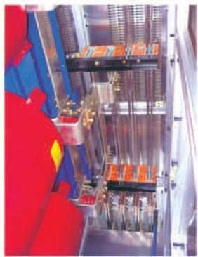
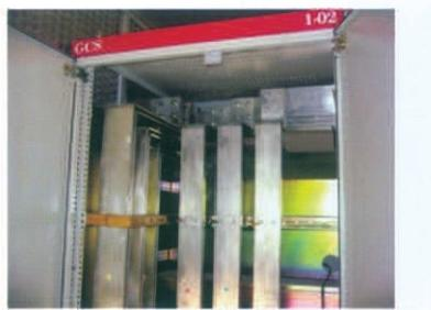
The functional compartments of the device are strictly separated, mainly including the Functional Unit Compartment, Busbar Compartment, and Cable Compartment. The functional role of each unit is relatively independent.
The device adopts the traditional technology of installing horizontal busbars on the top of the cabinet, enabling cable outlet channels both at the top and bottom of the Cable Compartment. This solves the problem that old products could not realize top and bottom cable outlet
■ Functional Units
A drawer serves as an independent functional unit.
Drawers are classified into 1/2 unit, 1 unit, 2 units, and 3 units. The height of 2-unit and 3-unit drawers is simply 2 times and 3 times that of 1-unit drawers, respectively. The height of one unit is 160mm or (200mm), and the width of a 1/2 unit is 280mm.
Drawers of functional units can be easily interchanged.
Each cabinet of the device can be configured with 11 drawers of 1 unit or 22 drawers of 1/2 unit.
For the incoming and outgoing lines of drawers, blade connectors of the same specification with different quantities are used based on the circuit current. Generally, one blade connector is rated for 125A.
The connection between 1/2-unit drawers and the Cable Compartment adopts backplane-structured adapters, while the connection between full-unit drawers and the Cable Compartment adopts rod-structured adapters.
The drawer panel is clearly marked with positions such as "Closed", "Open", "Test", and "Withdrawn", and the drawer is equipped with a mechanical interlocking device.
Feeder cabinets and motor control cabinets are equipped with dedicated Cable Compartments. The connection between the Functional Unit Compartment and the Cable Compartment is realized through adapters or adapter copper bars, which not only improves the reliability of cable use but also greatly facilitates users in cable arrangement and maintenance. The Cable Compartment has two optional width dimensions (240mm and 440mm), depending on the number of cables, cable cross-section, and user requirements for convenient installation and maintenance.
For functional units of the device: the number of auxiliary contact pairs is 32 pairs for 1 unit and above, and 20 pairs for 1/2 unit, which can meet the needs of users with automated systems and computer interface requirements.
Considering the safety of ordinary dry-type transformers and the cost-effectiveness of oil-immersed transformers, the device can be easily arranged in a row with dry-type transformers, and can also be conveniently connected to the low-voltage busbar of oil-immersed transformers.
With drawers as the main component, the device features both withdrawable and fixed types, which can be mixed and combined for optional selection.
The device is designed for both three-phase five-wire system and three-phase four-wire system. The design department can select either the PE+N or PEN configuration.
The cabinet protection class is IP30 or IP40, which can be selected according to user needs.
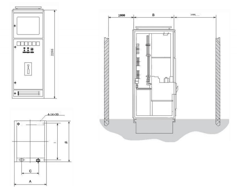
■ Dimension Series of Device Cabinets
Height (H) | Width (W) | Depth (D) |
2200 | 400 | 800, 1000 |
2200 | 600 | 800, 1000 |
2200 | 800 | 600, 800, 1000 |
2200 | 1000 | 600, 800, 1000 |
■ Installation and Usage
After the product arrives at the receiving location, first check whether the packaging is intact and undamaged. If any problem is found, promptly notify the contract-related departments to prepare commercial records, jointly analyze the causes, and complete certification and follow-up handling.
For products not to be installed immediately, they shall be placed in a suitable location and properly stored in accordance with the requirements of normal operating conditions and temporary storage regulations for electrical equipment.
The product shall be installed in accordance with the installation guide diagram (see attached drawing). The foundation channel steel and the bolts used for the bolt fixing method shall be prepared by the user. During main busbar connection, if there is surface unevenness due to transportation, storage, or other reasons, the surface must be leveled before connection and tightening.
When the device is installed individually or in a row, the deviations in verticality, cabinet surface unevenness, and gap between cabinets shall comply with the requirements specified in the table below.
Item No. | Item | Allowable Deviation (mm) |
1 | Verticality | 3.3 |
2 | Levelness | Top of Adjacent Cabinets | 2 |
Top of Cabinets in a Row | 5 |
3 | Unevenness | Side of Adjacent Cabinets | 1 |
Side of Cabinets in a Row | 5 |
4 | Gap Between Cabinets | 2 |
◎ Inspection and Testing of the Product Before Commissioning After Installation
Check whether the cabinet surface paint or other covering materials (e.g., plastic spraying) are damaged, and whether the interior of the cabinet is dry and clean;
Check whether the operating mechanisms of electrical components are flexible, without jamming or excessive operating force;
Check whether the main and auxiliary contacts of key electrical components have reliable and accurate on-off performance;
Check whether drawers or withdrawable mechanisms can be pulled and pushed smoothly and lightly, without jamming or collision;
Check whether the centerlines of the moving and fixed contacts of drawers or withdrawable mechanisms are aligned, whether the contacts are in tight contact, and whether the insertion depth of the main and auxiliary contacts meets the requirements;
Check whether mechanical interlocking or electrical interlocking devices act correctly, and whether locking and unlocking are reliable;
Check whether drawers of the same size can be interchanged conveniently, without jamming or collision. The grounding contacts between the drawer and the cabinet shall be in tight contact: when the drawer is pushed in, the grounding contacts of the drawer shall make contact before the main contacts; when the drawer is pulled out, the grounding contacts shall break contact after the main contacts;
Check whether the scales of instruments are complete, and whether the transformation ratio and polarity of transformers are correct;
Check whether the specifications of fuse elements comply with the requirements of engineering design;
Check whether the rated value and setting of protection devices are correct, and whether their operation is reliable;
Measure the insulation resistance with a 1000-volt megohmmeter; the resistance shall not be less than 1 MΩ;
Check whether the connection of each busbar is in good condition, and whether insulation supports, mounting parts and other accessories are installed firmly and reliably.
◎ Usage Precautions
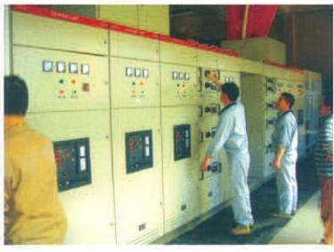
This device is a low-voltage distribution cabinet not suitable for wall-mounted installation, designed for front-side operation and double-sided maintenance. Only certified professional personnel are allowed to enter the maintenance channels or open the cabinet doors for operation, inspection, and maintenance;
After multiple switching operations (opening and closing), the contacts of air circuit breakers and molded case circuit breakers may suffer localized burning and carbon deposits, which increase contact resistance. Maintenance and repair shall be carried out in accordance with the circuit breaker operation manual;
After installation and maintenance, the isolation status between compartments and between functional units must be strictly checked to ensure good functional separation of the device and prevent the expansion of faults.
◎ Selection of Electrical Components
The device mainly uses electrical components with advanced technical performance indicators, which are now mass-produced domestically using imported technology:
Main Switches
For power incoming and feeder switches with a rating of 630A and above: The primary selection is the CW1 series; alternatively, the RMW1, TW30, AE, 3WE, or ME series can be used. If deemed necessary, imported series such as MT (ABB) or E (Schneider) can also be selected;
For feeder and motor control switches with a rating below 630A: The primary selection is the TG series and CM1 series; for molded case switches, the RMM1 series and TM30 series molded case circuit breakers can also be used;
AC Contactors: The primary selection includes the B series, LC1 series, and 3TB series contactors, along with supporting thermal relays and interlocking mechanisms;
Current Transformers: The BH series is selected;
Fuses: High breaking capacity fuses are used, including the Q series knife fuses and NT00 series;
To improve the dynamic stability of the main circuit, a dedicated CMJ-type combined busbar clamp and insulation supports for the GCS series are designed. These components are thermoformed using high-strength, flame-retardant synthetic materials, featuring high insulation strength, good self-extinguishing properties, and a unique structure. They can be adapted to busbars of different specifications by simply adjusting the modular spacers.
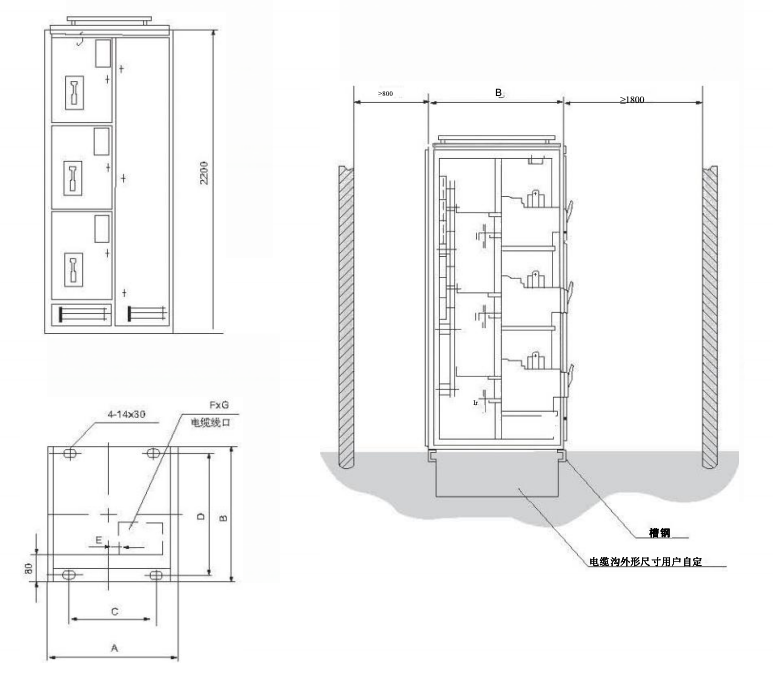
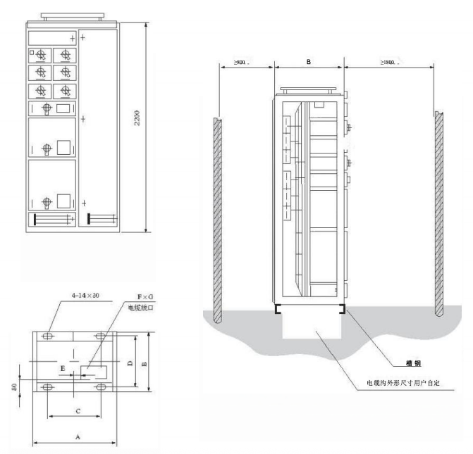
■ Attached Drawings
General Cabinet Code | A | B | C | D | Remarks |
GCS-TG1010-4 | 1000 | 1000 | 850 | 956 | Incoming Line Cabinet |
GCS-TG0810-4 | 800 | 1000 | 650 | 956 | Incoming Line Cabinet |
GCS-TG0808-4 | 800 | 800 | 450 | 756 | Incoming Line Cabinet |
GCS-TG0608-4 | 600 | 800 | 450 | 756 | Incoming Line Cabinet |
■ Attached Drawings
General Cabinet Code | A | B | C | D | E | FxG | Remarks |
GCS-TG1010-2 | 1000 | 1000 | 850 | 956 | 60 | 400×400 | Outgoing Line Cabinet |
GCS-TG0810-2 | 800 | 1000 | 650 | 956 | 160 | 200×400 | Outgoing Line Cabinet |
GCS-TG1008-2 | 1000 | 800 | 850 | 756 | 60 | 400×400 | Outgoing Line Cabinet |
GCS-TG0808-2 | 600 | 800 | 650 | 756 | 160 | 200×400 | Outgoing Line Cabinet |
■ Attached Drawings
General Cabinet Code | A | B | C | D | E | F×G | Remarks |
GCS-TG1006-1 | 1000 | 600 | 850 | 556 | 60 | 400×350 | Drawer Cabinet |
GCS-TG0806-1 | 800 | 600 | 650 | 556 | 160 | 200×350 | Drawer Cabinet |
■ Main Circuit Scheme
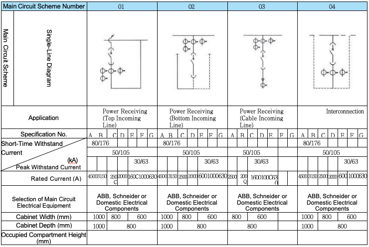
Note :
For feeder schemes, a zero-sequence current transformer can be added, and the zero-sequence current transformer shall be installed in the cable compartment
When the rated current of the power incoming line is 5000A, the cabinet width shall be increased to 1200mm accordingly
 English
  French
  Icelandic
  Georgian
  Slovak
  Slovenian
  Latvian
  Bosnian
  Ukrainian
  Serbian
  Croatian
  Belarusian
  Romanian
  Estonian
  Hungarian
  Czech
Czech  Catalan
  Norwegian
  Lithuanian
  Albanian
  Hindi
Hindi  Italian
  Finnish
  Arabic
  Danish
  Bulgarian
  Thai
Thai  Polish
  Swedish
  Greek
Greek  Portuguese
  Dutch
Dutch  Turkish
  Russian
  Deutsch
  Korean
  Japanese


")