■ Product Overview
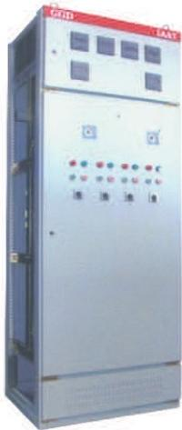
The GGD-type AC low-voltage power distribution cabinet is suitable for power users such as power plants, substations, industrial and mining enterprises. It is used in power distribution systems with AC 50Hz, rated operating voltage of 380V, and rated operating current up to 3150A, serving for power conversion, distribution, and control of power, lighting, and power distribution equipment.
The GGD-type AC low-voltage power distribution cabinet is a new-type low-voltage power distribution cabinet designed in line with the requirements of the competent authorities of the Ministry of Energy, a large number of power users, and design departments, adhering to the principles of safety, economy, rationality, and reliability. The product features high breaking capacity, excellent dynamic and thermal stability, novel and reasonable structure, practical electrical schemes, strong seriality and adaptability, and high protection class. It can be used as an upgraded replacement product.
The GGD-type AC low-voltage power distribution cabinet complies with standards such as IEC 60439 Low-Voltage Assembled Switchgear and Controlgear and GB 7251.1 Low-Voltage Assembled Switchgear and Controlgear.
■ Operating Conditions
The ambient air temperature shall not be higher than +40℃ or lower than -5℃, and the average temperature within 24 hours shall not exceed +35℃.
It is for indoor installation and use, and the altitude of the installation location shall not exceed 2000m.
The relative humidity of the ambient air shall not exceed 50% when the maximum temperature is +40℃; higher relative humidity is allowed at lower temperatures (e.g., 90% at +20℃). The impact of occasional condensation that may occur due to temperature changes shall be taken into account.
The inclination angle of the equipment relative to the vertical plane shall not exceed 5 degrees during installation.
The equipment shall be installed in locations free from severe vibration and impact, and in places that will not cause corrosion to electrical components.
■ Electrical Parameters
| Parameter Category | Specific Specifications |
| Rated Insulation Voltage | 660V |
| Rated Operating Frequency | 50Hz |
| Operating Voltage of Auxiliary Circuits | AC: 100V, 220V, 380V |
| DC: 100V, 220V |
| Rated Operating Current | GGD1: 400A, 600A (630A), 1000A |
| GGD2: 1000A, 1500A (1600A) |
| GGD3: 2000A, 2500A, 3150A |
| Rated Short-Circuit Strength | GGD1: Breaking Capacity = 15 kA, Peak Withstand Current = 30 kA |
| GGD2: Breaking Capacity = 30 kA, Peak Withstand Current = 63 kA |
| GGD3: Breaking Capacity = 50 kA, Peak Withstand Current = 105 kA |
■ Cabinet Body Structure Description
The framework is assembled by partial welding of 8Mf cold-formed steel. Its rigidity and load-bearing capacity both meet the installation requirements of electrical components. The frame is provided with mounting holes arranged at the moduli of D=20mm and E=100mm respectively to improve the universality of product assembly.
The main busbars are arranged at the upper rear part of the cabinet. The ZMJ-type busbar clamps adopted feature a modular combined structure, which is formed by thermal injection molding of high flame-retardant PPO material. They have high mechanical strength and insulation performance, and can withstand the dynamic and thermal stability impact of 50kA (effective value) and 105kA (peak value); the long-term allowable temperature can reach 120℃.
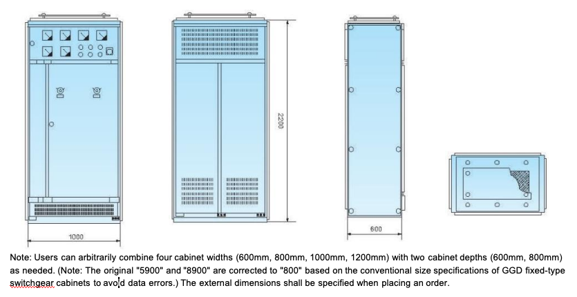
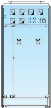
See the table below for the external dimensions of the framework (see the figure for the appearance):
For cabinets with a width of 1000mm and 1200mm, the front side adopts an asymmetric double-door structure with dimensions (800+200)mm and (800+400)mm respectively;
For cabinets with a width of 600mm and 800mm, the front side adopts a single-door structure;
The rear door of the 600mm-wide cabinet is a single-door structure, while the rear doors of the 800mm, 1000mm, and 1200mm-wide cabinets are of a symmetrical double-door structure.
This design not only provides protection against direct electric shock but also improves the overall aesthetics and strength, and facilitates the standardized production of the manufacturer.
The cabinet doors are connected to the frame via galvanized pivot hinges, enabling easy installation and disassembly. Rubber inserts are added at the folded edges of the doors; when the doors are closed, the inserts between the doors and the cabinet body have a certain compression stroke to prevent direct collision between the door edges and the cabinet body, and improve the protection class of the doors.
The instrument door with electrical components installed is connected to the frame via multi-strand flexible copper wires. The mounting parts inside the cabinet are connected to the cabinet frame via grounding knurled screws, forming a complete grounding protection circuit.
The protection class of the front, rear, top, and side ends of the cabinet body reaches IP30, and can also be selected between IP20 and IP40 according to user requirements.
To enhance ventilation and heat dissipation, ventilation and heat dissipation holes are provided at the lower part, upper rear part, and top of the cabinet body, forming a natural air duct during the cabinet's operation and ensuring good heat dissipation performance. The heat dissipation holes are sealed with steel wire mesh to ensure the cabinet's protection class.
The top cover of the cabinet body can be removed when necessary, facilitating the on-site assembly and adjustment of the main busbars. Lifting rings are installed at the four corners of the cabinet top for easy hoisting and transportation.
The coating layer of the cabinet body is sprayed with polyester baking paint, which eliminates glare and has strong adhesion. The mounting parts inside the cabinet are all treated with galvanization and passivation to improve the "three-proof" performance (moisture-proof, corrosion-proof, and mildew-proof).
| Height | Width | Depth |
| GGD1、GGD2 | 2200 | 6008001000 | 600 |
| GGD3 | 2200 | 80010001200 | 600800 |
■ Outline Sketch
■ Installation and Usage
◎ Product Installation
The product shall be installed in accordance with the installation diagram. The foundation channel steel and bolts shall be prepared by the user.
◎ Inspection and Testing Items to Be Conducted After Installation and Before Commissioning
A. Check whether the coating film on the cabinet covering layer is peeled off, and whether the interior of the cabinet is dry and clean.B. Check whether the operating mechanism of electrical components is flexible, and there shall be no jamming or excessive operating force.C. Check whether the on-off action of main electrical components is reliable and accurate, and whether the on-off action of auxiliary contacts is reliable and accurate.D. Check whether the transformation ratio and polarity of current transformers match the instrument indication (Note: "变化" in the original text is corrected to "transformation ratio"—a common technical term for transformers, ensuring accuracy).E. Check whether the busbar connections are in good condition, and whether the insulating supports, mounting parts, and accessories are installed firmly and reliably.F. Check whether the auxiliary contacts meet the requirements, whether the specification of fuse elements is correctly selected, and whether the setting values of relays conform to the design requirements and their actions are accurate (Note: "溶芯" in the original text is corrected to "fuse elements"—the correct term for fuse cores).G. Check whether the circuit contacts comply with the requirements of the electrical schematic diagram.H. Check whether the protective circuit system meets the requirements.I. Measure the insulation resistance with a 500V megohmmeter (Note: "光欧表" in the original text is corrected to "megohmmeter"—the standard instrument for measuring insulation resistance), and the value shall not be less than 1 MΩ.
◎ Usage Precautions
A.This product is a low-voltage power distribution cabinet that is floor-mounted (not wall-mounted), designed for single-side (front-side) operation and double-side door opening for maintenance. Only qualified professional personnel are allowed to access the maintenance access or open the cabinet doors for operation, inspection, and maintenance.B. After multiple switching operations (closing and opening), the main contacts of air circuit breakers may be partially burned and form carbon deposits, which will increase the contact resistance. Therefore, the air circuit breakers shall be maintained and inspected regularly in accordance with their operation manuals.
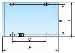
| Product Code | A | B | C | D |
| GGD06 | 600 | 600 | 450 | 556 |
| GGD06A | 600 | 800 | 450 | 756 |
| GGD08 | 800 | 600 | 650 | 556 |
| GGD08A | 800 | 800 | 650 | 756 |
| GGD10 | 1000 | 600 | 850 | 556 |
| GGD10A | 1000 | 800 | 850 | 756 |
| GGD12 | 1200 | 800 | 1050 | 756 |
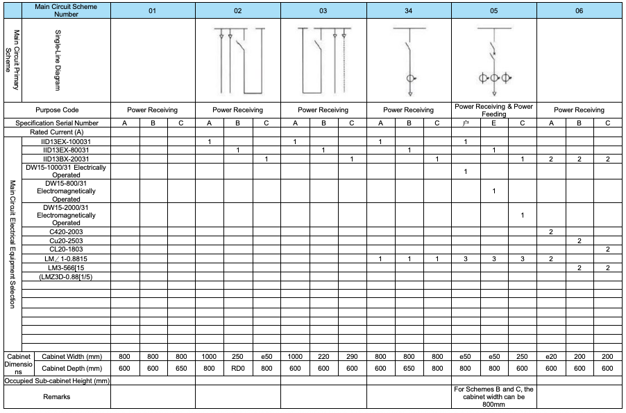
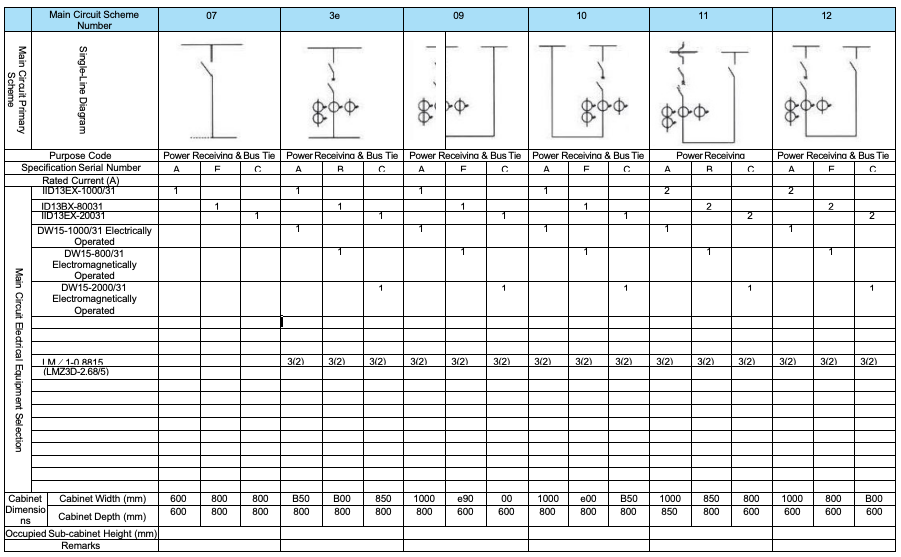
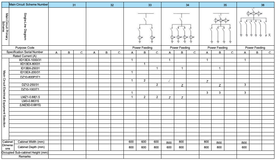
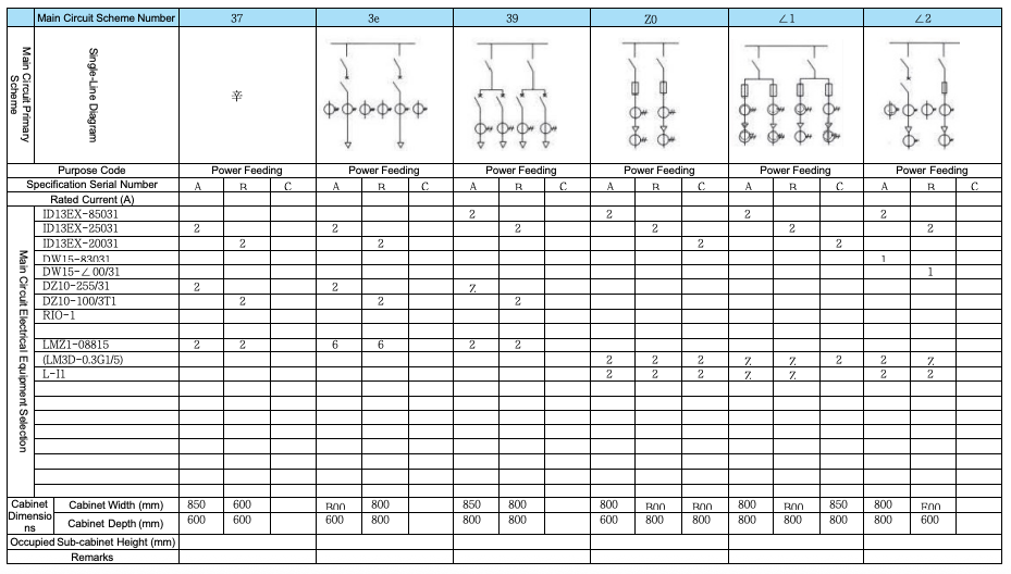
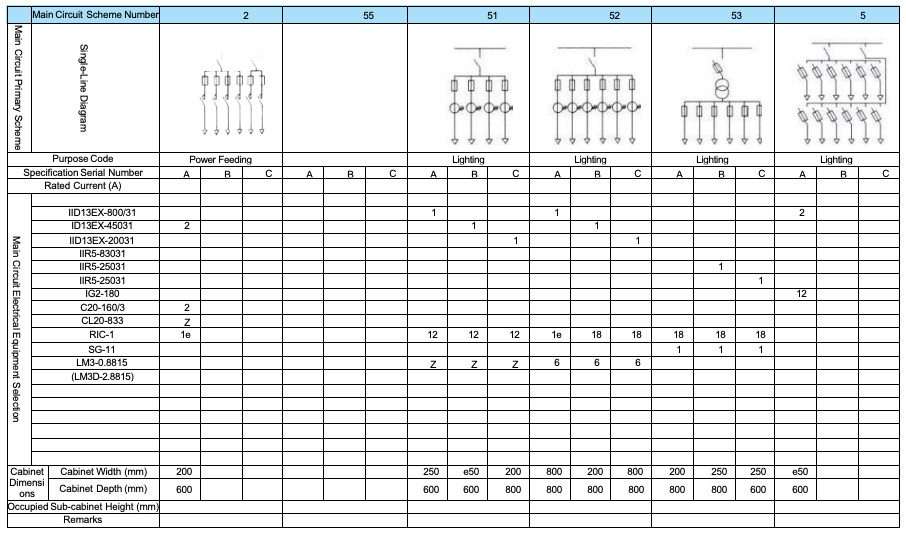
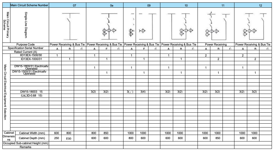
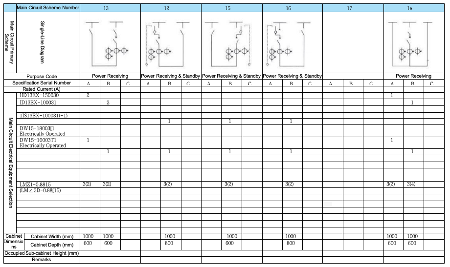
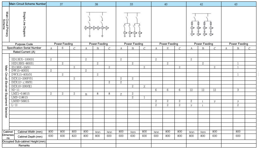
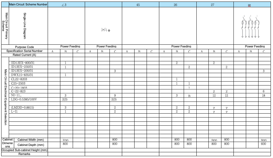
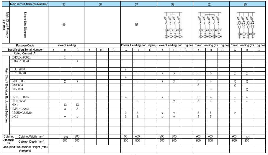
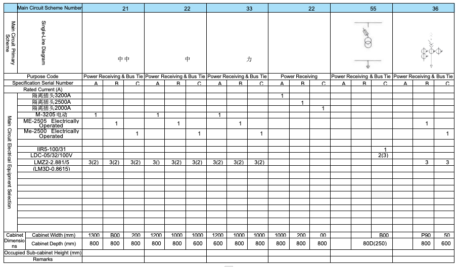
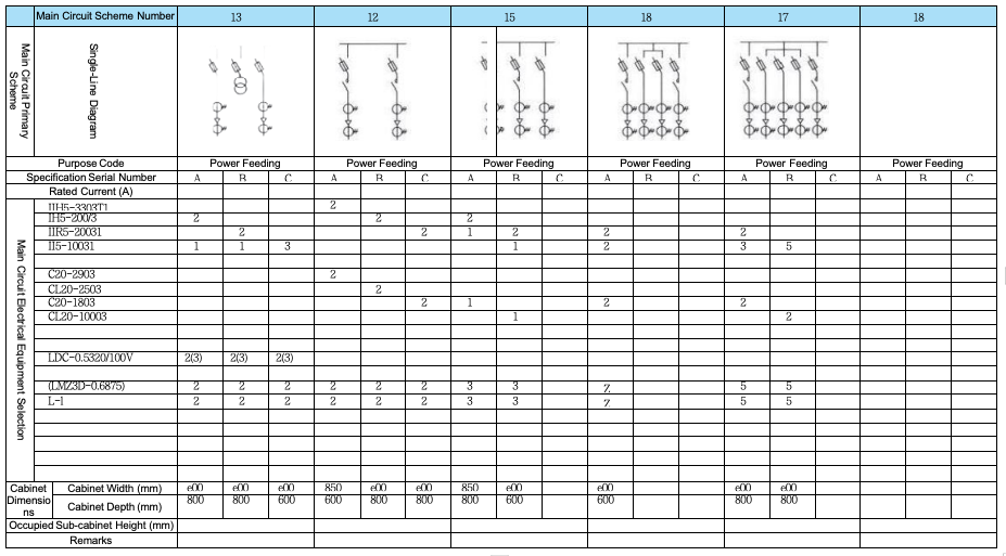
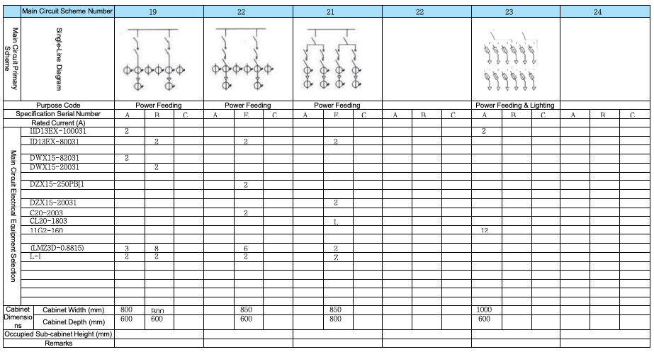
Main Circuit Scheme
Main Circuit Scheme for GGD1 Type
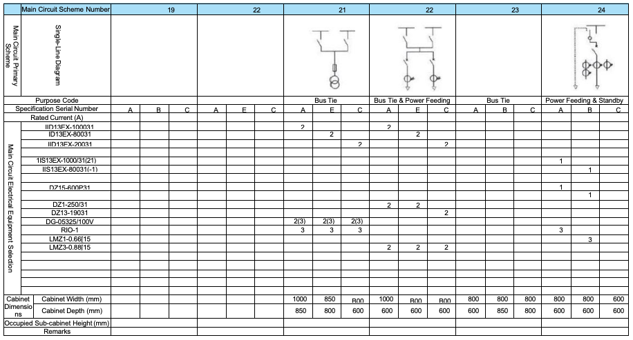
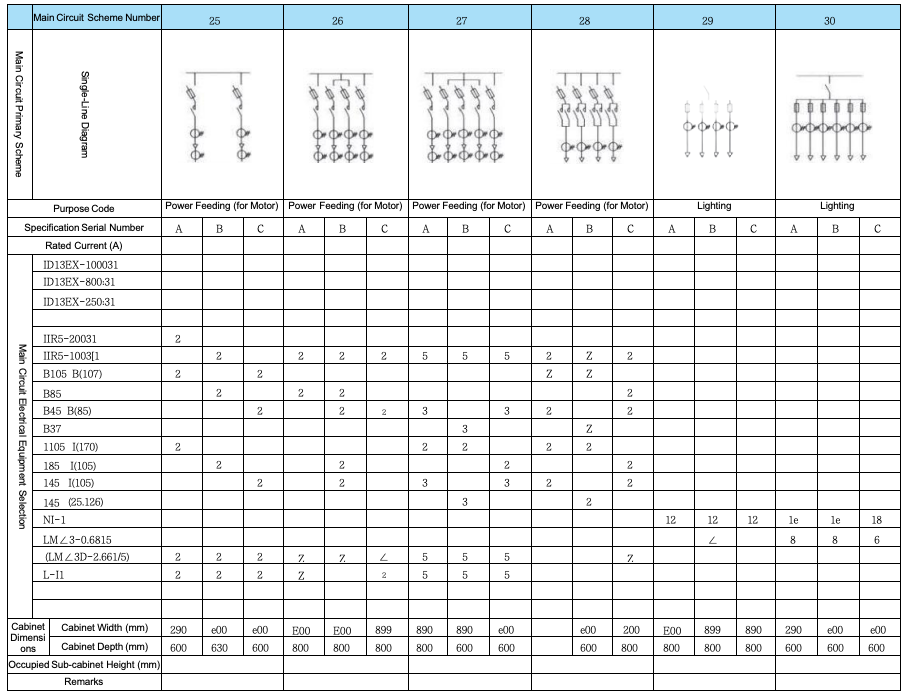
GGD2 Main Circuit Scheme
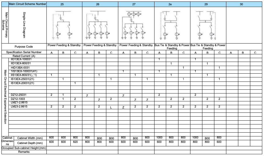
Main Circuit Scheme for GGD3 Type
 English
  French
  Icelandic
  Georgian
  Slovak
  Slovenian
  Latvian
  Bosnian
  Ukrainian
  Serbian
  Croatian
  Belarusian
  Romanian
  Estonian
  Hungarian
  Czech
Czech  Catalan
  Norwegian
  Lithuanian
  Albanian
  Hindi
Hindi  Italian
  Finnish
  Arabic
  Danish
  Bulgarian
  Thai
Thai  Polish
  Swedish
  Greek
Greek  Portuguese
  Dutch
Dutch  Turkish
  Russian
  Deutsch
  Korean
  Japanese


")