KYN28A-12 Type
Safe and Reliable Metal-Clad Medium-Voltage Withdrawable Switchgear
■Product Overview
The KYN28A-12 metal-clad medium-voltage withdrawable switchgear is suitable for 3-phase AC 50Hz / 7.2-12KV single-busbar and single-busbar section power systems. It is used for receiving and distributing electrical energy, as well as controlling, protecting, and monitoring circuits. This switchgear complies with domestic and international standards such as IEC-60298, GB3906, and DL404.
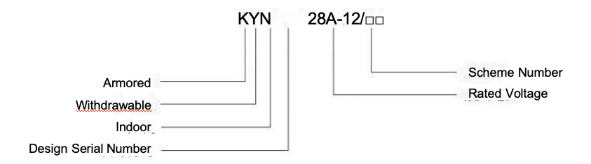
■Product Model and Its Interpretation
■Operating Environment
◎Ambient Temperature: Upper limit: +40℃; Lower limit: -10℃;
◎Altitude: Not exceeding 1000m;
◎Relative Humidity: Daily average ≤ 95%, Monthly average ≤ 90%;
◎Seismic Intensity: Not exceeding Grade 8;
◎Installed in places free from fire, explosion hazards, severe pollution, chemical corrosion, and violent vibration.
Note: If the above operating conditions are exceeded, please consult the manufacturer.
■Features
◎Fully metal-armored and enclosed, which can effectively prevent the spread of accidents;
◎Complete isolation between low-voltage parts and high-voltage parts;
◎After the door is opened, the protection level reaches IP4X, which can effectively prevent humans and external solids from approaching live parts and moving parts, ensuring personal safety and reliable operation of the equipment;
◎Simple and effective interlocking to prevent misoperation;
◎The cable compartment has sufficient space to connect multiple cables, facilitating installation and maintenance;
◎Good interchangeability of handcarts, making the replacement of circuit breakers very easy.
■Technical Parameters
Item | Unit | Data |
Circuit Breaker Cabinet | F-C Cabinet |
Rated Voltage | kV | 7.2, 12 | 7.2, 12 |
1min Power Frequency Withstand Voltage | kV | 32, 42 | 32, 42 |
Lightning Impulse Withstand Voltage | kV | 60, 75 | 60, 75 |
Rated Frequency | Hz | 50 | 50 |
Rated Current of Main Busbar | A | …4000 | …4000 |
Rated Current of Branch Busbar | A | …4000* | …400 |
Rated Short-Time Withstand Current (RMS) 4s** | kA | …40 | 4kA/4S |
Rated Peak Withstand Current (Peak)** | kA | …100 | 10 |
Enclosure Protection Class | | IP4X | IP4X |
*: For circuit breakers with rated current of 3150A and above, forced air cooling is adopted for the breaker compartment.
**: The thermal stability and dynamic stability current of the current transformer are related to the transformation ratio, which should be confirmed in detail when placing an order.
■Overall Dimensions and Weight
Item | Specification |
Height | 2200mm |
Width | Rated Current ≤ 1250A: 800 (650*) mm |
| Rated Current ≤ 1600A: 1000mm |
Depth | Front Maintenance: 1350mm |
| Double-Side Maintenance: 1500/1560mm |
F-C Cabinet (W × H × D) | 650 × 2200 × 1560mm |
Weight | 800-1200kg |
*: This dimension can be used when equipped with VD4 circuit breaker.
■Introduction to the Structure
This switchgear consists of two main parts: the cabinet body and the handcart.
The cabinet body is assembled with bolts, and its outer shell and internal partitions are made of anti-corrosion steel plates. The cabinet body is composed of four different functional units: handcart compartment, busbar compartment, cable compartment, and low-voltage compartment. There are two types of cabinet structures: front-maintenance structure and double-side maintenance structure.
Withdrawable units can be classified by purpose as follows:
• Circuit breaker handcart
• Voltage transformer handcart
• Isolation handcart
• Metering handcart
• Fuse handcart, etc.
| Internal Structure Diagram of Front-Maintenance Type Cabinet (Equipped with Conventional Current Transformers) | 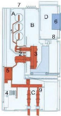
| A: Busbar Compartment |
| B: Circuit Breaker Compartment |
| C: Cable Terminal Compartment |
| D: Low-Voltage Compartment |
| 1: Busbar |
| 2: Static Contact Box |
| 3: Circuit Breaker |
| 4: Earthing Switch |
| 5: Current Transformer |
| 6: Control and Protection Unit |
| 7: Pressure Relief Plate |
| 8: Secondary Plug |
| 9: Cable Terminal |
| Internal Structure Diagram of Front-Maintenance Type Cabinet (Equipped with Tubular Current Transformers) | 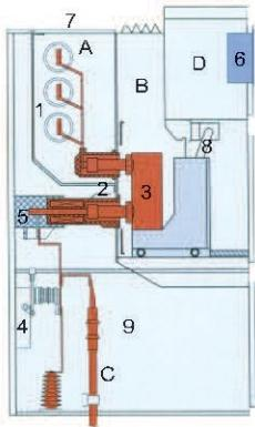
| A: Busbar Compartment |
| B: Circuit Breaker Compartment |
| C: Cable Terminal Compartment |
| D: Low-Voltage Compartment |
| 1: Busbar |
| 2: Static Contact Box (integrated with transformer) |
| 3: Circuit Breaker |
| 4: Earthing Switch |
| 5: Adapter |
| 6: Control and Protection Unit |
| 7: Pressure Relief Plate |
| 8: Secondary Plug |
| 9: Cable Terminal |
| Internal Structure Diagram of Double-Side Maintenance Type Cabinet | 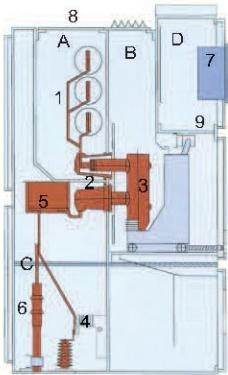
| A: Busbar Compartment |
| B: Circuit Breaker Compartment |
| C: Cable Terminal Compartment |
| D: Low-Voltage Compartment |
| 1: Busbar |
| 2: Static Contact Box |
| 3: Circuit Breaker |
| 4: Earthing Switch |
| 5: Current Transformer |
| 6: Cable Terminal |
| 7: Control and Protection Unit |
| 8: Pressure Relief Plate |
| 9: Secondary Plug |
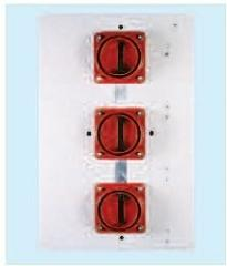
■Handcart Compartment
• Guide rails are installed in the handcart compartment to ensure the stable and reliable movement of the handcart inside the cabinet.
• Metal shutters automatically open and close as the handcart enters or exits. The upper and lower shutters can be opened separately, facilitating operation and maintenance while ensuring personal safety.
• The handcart can be operated when the handcart compartment door is closed. Through the inspection window, the position of the handcart, the closing/opening indication of the circuit breaker, and the energy storage status indication can be observed.
■Cable Compartment
• Usable for connecting:
Single-core cables: Up to 6 cables per phase
Three-core cables: Up to 3 cables per phase
• The cable connection height is above 650mm.
• Optional components:
Current transformer, Voltage transformer, Quick earthing switch, Arrester, Zero-sequence current transformer, Live display device
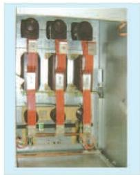
■Busbar Compartment
• Depending on the rated current, 1 to 3 copper bars are used for the main busbar.
• Adjacent busbar compartments are isolated by bushings and metal partitions, which can effectively prevent the spread of accidents.
• The main busbar and branch busbars are all covered with heat-shrinkable insulating sleeves.
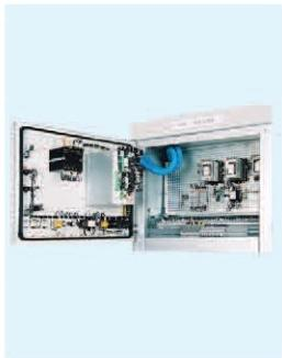
■Low-Voltage Compartment
• Various secondary equipment can be installed in the low-voltage compartment and on its door panel according to different requirements.
• The control busbar is installed on the top plate of the low-voltage compartment and covered with a rotatable partition, facilitating on-site installation.
■Interlocking
The KYN28A-12 switchgear is equipped with a series of interlocking devices, which fundamentally prevent dangerous situations and operations that may cause serious consequences, thus effectively ensuring the safety of operating personnel and the switchgear itself. The following operations of the switchgear can only be performed when the relevant interlocking conditions are met; otherwise, the operation will be blocked.
• Moving the handcart from the test position to the working position:
The circuit breaker or contactor is in the "open" position
The earthing switch is in the "open" position
• Pulling the handcart back from the working position to the test position:
The circuit breaker or contactor is in the "open" position
• Operating the circuit breaker or contactor:
The handcart is locked in the test position or working position
• Operating the earthing switch:
The handcart is locked in the test position
The cable compartment door is closed
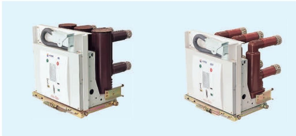
Main Technical Parameters of VG1 (ZN63B-12) Type Vacuum Circuit Breaker
Rated Voltage | kV | 12 |
Rated Current | A | 630, 1250 | 630, 1250 | 1600, 2000 | 1250, 1600, 2000 | 2000, 3150*, 4000* |
Rated Frequency | Hz | 50 |
Rated Short-Circuit Breaking Current (RMS) | kA | 20 | 25 | 31.5 | 40 | 50 |
Rated Short-Circuit Making Current (RMS) | kA | 50 | 63 | 80 | 100 | 125 |
Rated Thermal Stability Current | kA | 20 | 25 | 31.5 | 40 | 50 |
Rated Dynamic Stability Current | kA | 50 | 63 | 80 | 100 | 125 |
Number of Rated Short-Circuit Breaking Operations | Times | 50** |
1min Power Frequency Withstand Voltage | kV | 42 |
Lightning Impulse Withstand Voltage | kV | 75 |
Rated Breaking Current of Single Capacitor Bank | A | 630 |
Rated Breaking Current of Back-to-Back Capacitor Banks | A | 400 |
Rated Making Inrush Current of Capacitor Bank | kA | 12.5 (t < 1000Hz) |
DC Component Percentage of Breaking Current | - | 50%*** |
Rated Operating Sequence | - | O-0.3s-CO-180s-CO(≤31.5kA)
O-180s-CO-180s-CO(≥40kA) |
3150A, 4000A: Forced air cooling
** ≥40kA: 30 times
*** ≥40kA: 40%
Main Technical Parameters of VD4 Type Vacuum Circuit Breaker

Rated Voltage | kV | 12 |
Rated Current | A | …4000* |
Rated Frequency | Hz | 50 |
Rated Short-Circuit Breaking Current | kA | …50 |
Rated Short-Circuit Making Current (Peak) | kA | ..125 |
Rated Short-Time Withstand Current (Peak) | kA | ….50 |
Rated Peak Withstand Current (Peak) | kA | .…125 |
1min Power Frequency Withstand Voltage | kV | 42 |
Lightning Impulse Withstand Voltage | kV | 75 |
Rated Operating Sequence | - | O-0.3s-CO-180s-CO (≤31.5kA); O-180s-CO-180s-CO (≥40kA) |
Forced air cooling is adopted.
** 4 seconds at 31.5kA.
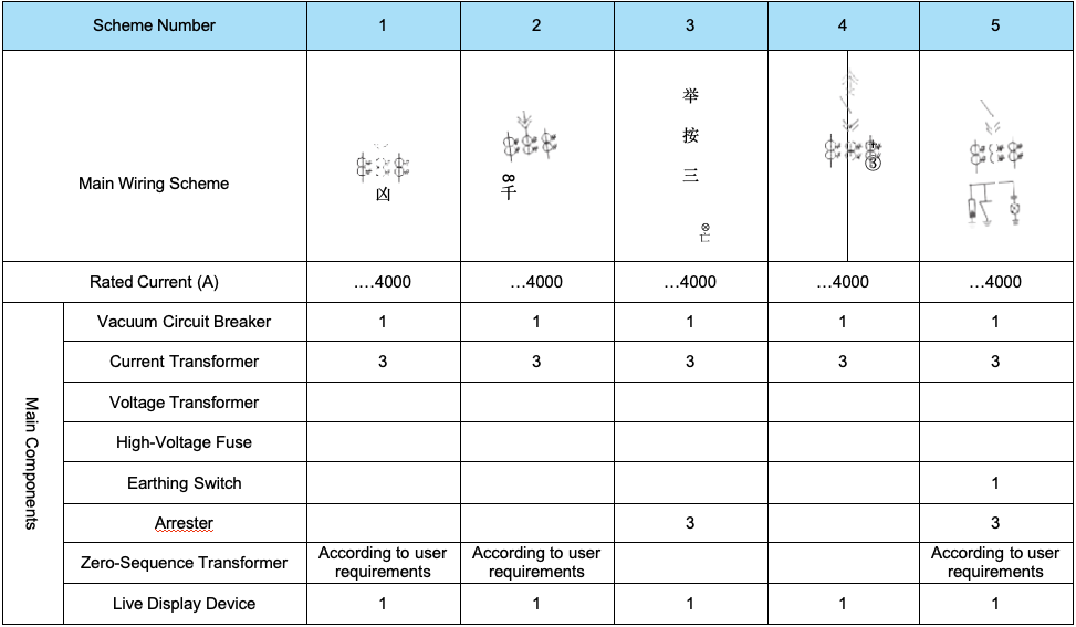
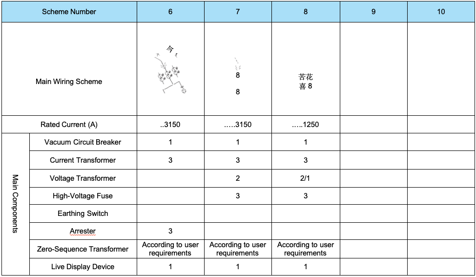
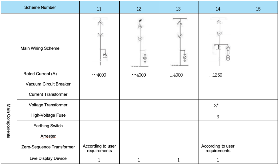
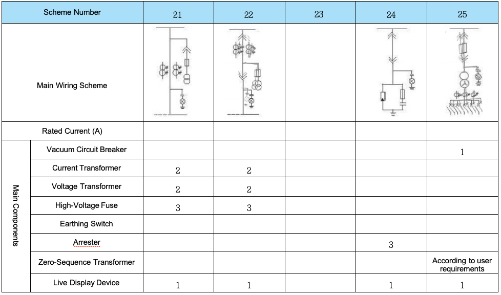
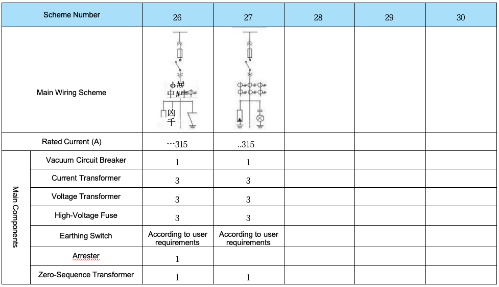
■Main Circuit Scheme

■ Overall Dimension Diagram of Switchgear

| Switchgear Parameter | Width (mm) |
| Rated Current ≤ 1250A | 800 |
| 1250A < Rated Current ≤ 4000A | 1000 |
| Station Transformer ≤ 30kVA | 1000 |
| F-C Cabinet | 650/800 |
■ Single-Row Arrangement Diagram of Switchgear
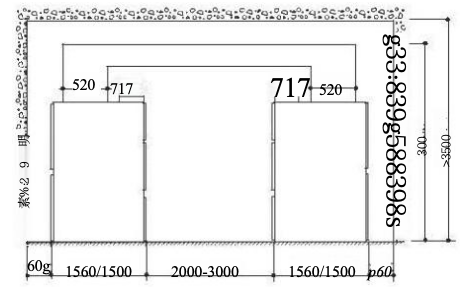
■ Opposite-Row Arrangement and Busbar Bridge Diagram of Switchgear
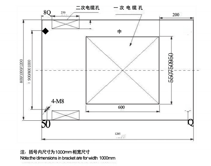
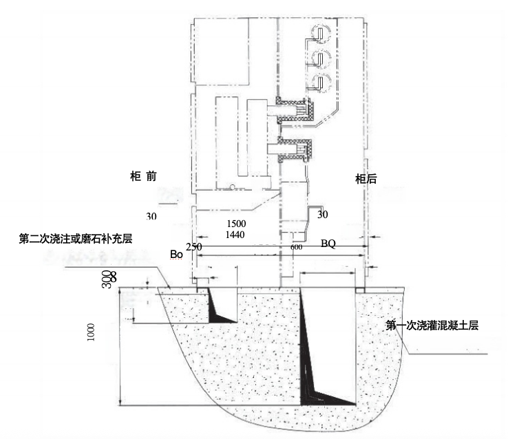
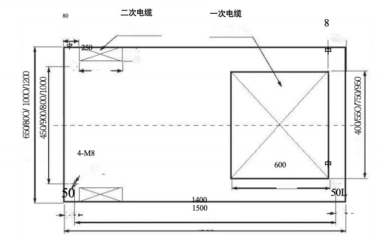
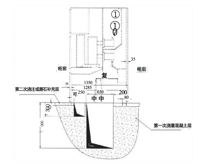
■ Installation Foundation Diagram of KYN28A-12 (Depth: 1500mm)
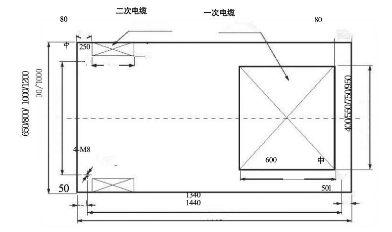
■ Floor Opening and Fixing Points of KYN28A-12 (Depth: 1500mm)
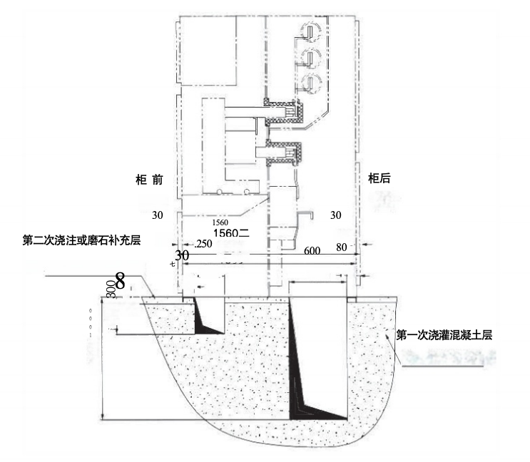
■ Installation Foundation Diagram of KYN28A-12 (Depth: 1560mm)
■ Floor Opening and Fixing Points of KYN28A-12 (Depth: 1560mm)
■ Installation Foundation Diagram of KYN28A-12 (Depth: 1350mm)
■ Floor Opening and Fixing Points of KYN28A-12 (Depth: 1350mm)
■ Instructions for Product Ordering
The following technical documents shall be provided by the user when placing an order:
◎ Single-line system diagram of the primary main wiring scheme and the model/specification of the main busbar;
◎ Secondary schematic diagram and terminal arrangement diagram for each cabinet; if there is no terminal arrangement diagram, it shall be arranged by the manufacturer;
◎ Layout diagram of the secondary small busbar and the type of small busbar;
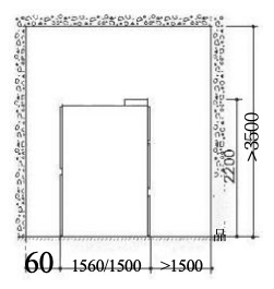
◎ Plan layout diagram and relevant cross-sectional diagrams of the power distribution room;
◎ If a busbar bridge (inter-cabinet busbar bridge or wall-cabinet busbar bridge, protection class: IP2X) is required, the span and height dimensions shall be provided;
◎ Summary table of electrical equipment;
◎ Regional special requirements and special operating environments shall be specified when placing the order;
◎ If other or additional accessories and spare parts are required, their types and quantities shall be specified.
 English
  French
  Icelandic
  Georgian
  Slovak
  Slovenian
  Latvian
  Bosnian
  Ukrainian
  Serbian
  Croatian
  Belarusian
  Romanian
  Estonian
  Hungarian
  Czech
Czech  Catalan
  Norwegian
  Lithuanian
  Albanian
  Hindi
Hindi  Italian
  Finnish
  Arabic
  Danish
  Bulgarian
  Thai
Thai  Polish
  Swedish
  Greek
Greek  Portuguese
  Dutch
Dutch  Turkish
  Russian
  Deutsch
  Korean
  Japanese


")